Compex Systems SP6.0: instruction
Class: Tourism, sport and recreation
Type:
Manual for Compex Systems SP6.0
Instruction for use
Mode d’emploi
Anweisungen
Istruzioni
Instrucciones
Instructies
Instruções
Инструкция
Bruksanvisning

Instructions

EN
TABLE OF CONTENTS
1. Explanation of symbols 02
2. How does electrostimulation work? 03
3. How does MI technology work (Muscle Intelligence)? 05
4. Instructions 07
Composition of kits and accessories 07
Device description 08
First use 10
Device function 11
Charging 25
5. Troubleshooting 29
6. Device maintenance 33
Guarantee 33
Maintenance 33
Storage/transport and use 33
Disposal 33
7. Technical specifications 34
General information 34
Neurostimulation 34
RF data 35
Standards 35
Information about electromagnetic compatibility (EMC) 35
8. EMC table 36
It is strongly recommended to read these instructions and the contra-indications and safety
measures carefully before using your stimulator.
01
EN
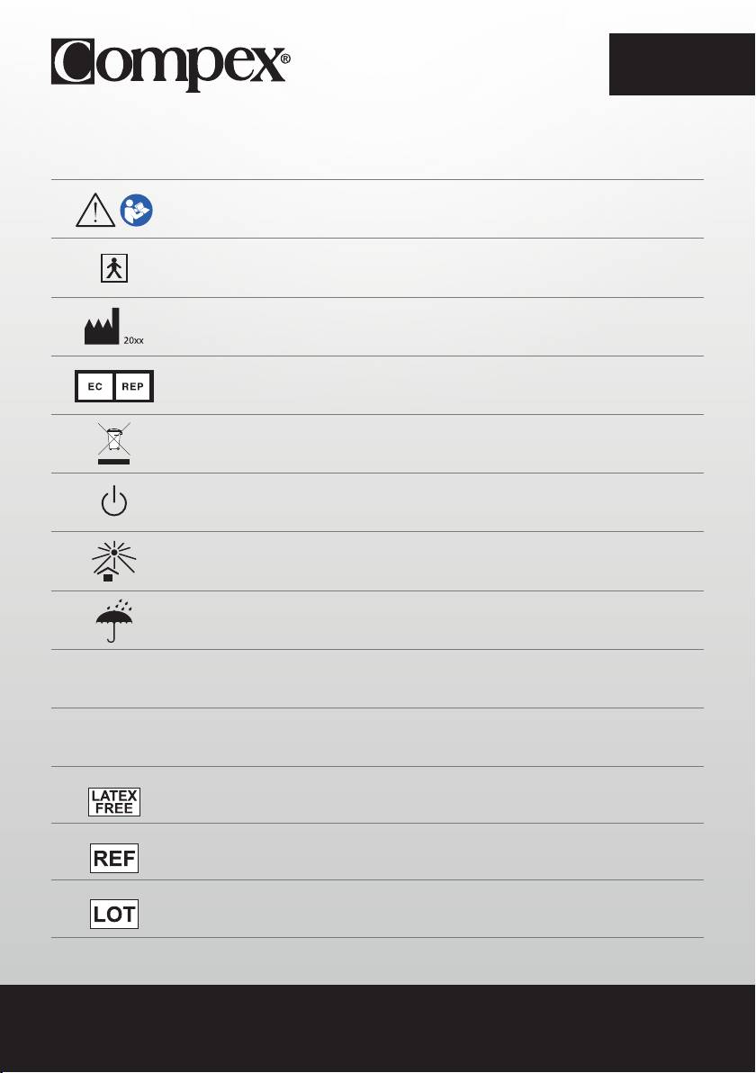
1. EXPLANATION OF SYMBOLS
See the instructions
The stimulator is a category II device with built-in power supply and BF applied parts type.
Manufacturer’s name and address and date of manufacture
Name and address of approved representative in the European Community
This device must be separated from household waste and sent to special recycling plants
The stand-by button is multi-functional
Protect from sunlight
Store in a dry place
IP20
Protected against solid bodies with a diameter equal to or greater than
On the unit
12.5 mm (0.5 po.)
IP02
IP02 on the carrying case means: Protected from the ingress of water droplets from a shower of
On the case
rain.
Latex-free
Reference number
Batch number
02

EN
2. HOW DOES ELECTROSTIMULATION WORK?
Electrostimulation involves stimulating nerve fibres by electrical impulses transmitted by electrodes. The
electrical impulses produced by Compex stimulators are high-quality impulses that are safe, comfortable
and effective and stimulate various types of nerve fibres:
1. Motor nerves to stimulate a muscle response referred to as electrical muscle stimulation (EMS).
2. Certain types of sensitive nerve fibres to obtain analgesic effects or pain relief.
1. STIMULATION OF MOTOR NERVES (EMS)
With voluntary activity, the brain orders muscles to contract and a command is then sent to nerve fibres
in the form of an electrical signal. This signal is then sent to muscle fibres, which contract. The principle
of electrostimulation correctly reproduces the process involved in a voluntary contraction. The stimulator
sends an electrical impulse to nerve fibres to excite them. This excitation is then transmitted to muscle
fibres and results in a mechanical response (= a twitch). This is the basic requirement for muscular
contraction. The muscular response is to all intents and purposes identical to the muscular work
controlled by the brain. In other words, the muscle does not distinguish between a command sent by the
brain or the stimulator.
Programme settings (number of impulses per second, duration of contraction, rest time, total programme
duration) subject the muscle to various types of workout, depending on the muscle fibre. Various types
of muscle fibres can be identified depending on their respective contraction speeds: slow, intermediate
and rapid fibres. A sprinter clearly has more rapid fibres and a marathon runner has more slow fibres.
With good knowledge of human physiology and perfect control of stimulation settings in the various
programmes, muscular workout can be very accurately directed to achieve the desired objective
(muscular strengthening, increased blood circulation, firming, etc.).
03

EN
2. STIMULATION OF SENSORY NERVES
Electrical impulses can also excite sensory nerve fibres to obtain analgesic effects or pain relief.
Stimulating tactile sensory nerve fibres blocks pain being transmitted to the nervous system. Stimulating
another type of sensory fibre increases the production of endorphins and therefore reduces pain. With
pain relief programmes, electrostimulation can be used to treat acute or chronic localised pain and
muscle pain.
Note: Do not use pain relief programmes for an extended period without medical advice.
BENEFITS OF ELECTROSTIMULATION
Electrostimulation is a very effective method for making muscles work:
• with a significant improvement in various muscle qualities
• with no cardiovascular or mental fatigue
• with limited stress exercised on joints and tendons. Electrostimulation thereby enables more muscular
workout than voluntary activity.
For optimum results, Compex recommends supplementing your electrostimulation sessions with other
exercise, such as:
• regular physical exercise
• balanced and healthy diet
• balanced life style
04

EN
3. HOW DOES MI TECHNOLOGY WORK
(MUSCLE INTELLIGENCE)?
N.B.: The activation/deactivation of MI functions is performed via the Settings menu
MI-SCAN
Just before starting a workout session, the MI-scan function probes the chosen muscle group and
automatically adjusts the stimulator settings to the excitability of this area of the body, depending on your
physiology.
This function results in, at the start of the programme, a short test sequence during which measurements are
taken.
At the end of the test, intensities must be increased to start the programme.
MI-TENS
The MI-tens function limits unwanted muscle contractions in painful areas.
With each intensity increase, a test phase occurs and if a muscular contraction is detected, the device
automatically reduces the intensity of the stimulation.
This function is only accessible in the TENS, Epicondylitis and Tendinitis programmes.
MI-RANGE
The MI-range function allows the user to select the ideal level of stimulation intensity for recovery, massage,
capillarisation or even muscle pain programmes.
At the beginning of the programme, the device prompts the user to increase stimulation intensity. During this
increase, the device analyses the response of each stimulated muscle, and deduces their optimal level. As
soon as a muscle reaches its optimal level, the related channel is automatically deselected and the stimulation
intensity cannot be increased. To recover control, simply re-select the channel in question and raise or lower
the stimulation intensities.
MI-AUTORANGE
The MI-autorange function pursues the same objective as MI-range except that in this case everything is
done automatically.
At the beginning of the programme, a single press of the up key of the multifunction pad allows the device to
automatically increase the stimulation intensities until it detects the ideal level of intensity. Pressing the down
key of the multifunction pad cancels the MI-autorange function. The device then goes into manual mode and
intensities must be managed by the user.
05
EN
MI-ACTION
The MI-action function allows you an electro-induced contraction to be initiated by means of a voluntary
action. Thus the electro-induced contraction is perfectly controlled, the workout becomes more comfortable,
more thorough and more complete.
At the end of each active rest phase the remote control emits a beep. From this point the start of voluntary
contraction is possible. If no voluntary contraction has occurred after a certain period of time, the device will
automatically pause.
This work mode is available only for programmes inducing powerful muscle contractions.
N.B.: To function properly, the MI-action function needs good muscle twitches during the active rest phase.
If they are not significant enough, the device emits beeps and a + sign appears on the channels. Similarly, in
order to render these twitches possible, it is imperative that muscles be well relaxed during the rest phase.
At the end of each contraction phase, it is necessary to ensure that you return to a position allowing for best
muscle relaxation.
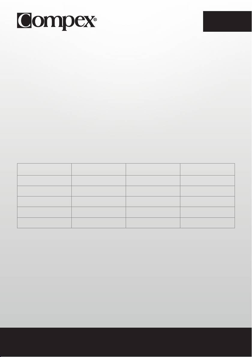
The table below shows which functions are available with each device.
SP 6.0 SP 8.0 FIT 5.0
MI-SCAN
✓ ✓ ✓
MI-TENS -
✓
-
MI-RANGE
✓
-
✓
MI-AUTORANGE -
✓
-
MI-ACTION -
✓
-
06
EN
4. INSTRUCTIONS
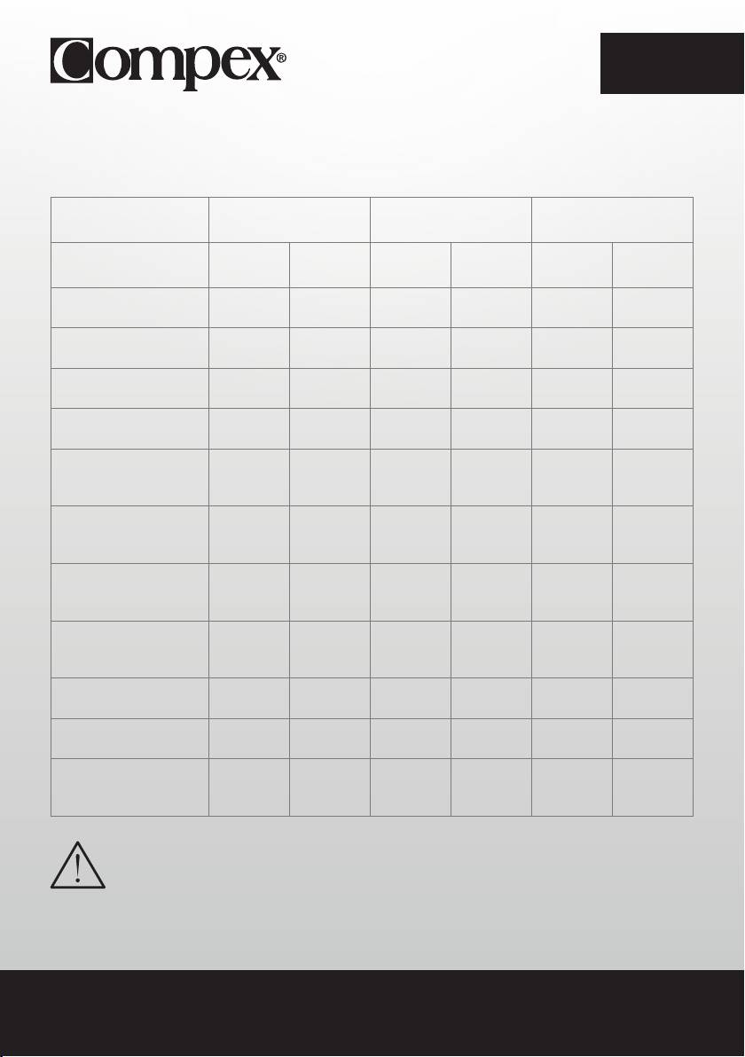
COMPOSITION OF KITS AND ACCESSORIES
SP 6.0 SP 8.0 FIT 5.0
REF QTY REF QTY REF QTY
REMOTE CONTROL 001047 1 001046 1 001048 1
MODULES 001061 4 001061 4 001055 2
DOCKING STATION 001068 1 001068 1 001073 1
CHARGER 64902X 1 64902X 1 00108X 1
BAG OF SMALL 5X5
42215 2 42215 2 42215 1
ELECTRODES
BAG OF LARGE 5X10
42216 2 42216 2 42216 1
ELECTRODES, 2 SNAP
BAG OF LARGE 5X10
42222 2 42222 2 42222 2
ELECTRODES, 1 SNAP
INSTRUCTIONS ON
880054 1 880054 1 880054 1
CD-ROM
QUICK START GUIDE 885625 1 885625 1 885625 1
CARRY CASE 680043 1 680042 1 680043 1
REMOTE CONTROL
NA NA 1094 1 NA NA
PROTECTION SLEEVE
Only use this device with cables, electrodes, battery, power adaptor and accessories
recommended by Compex.
07
EN
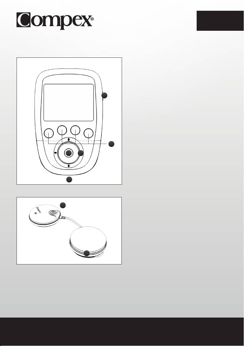
DEVICE DESCRIPTION
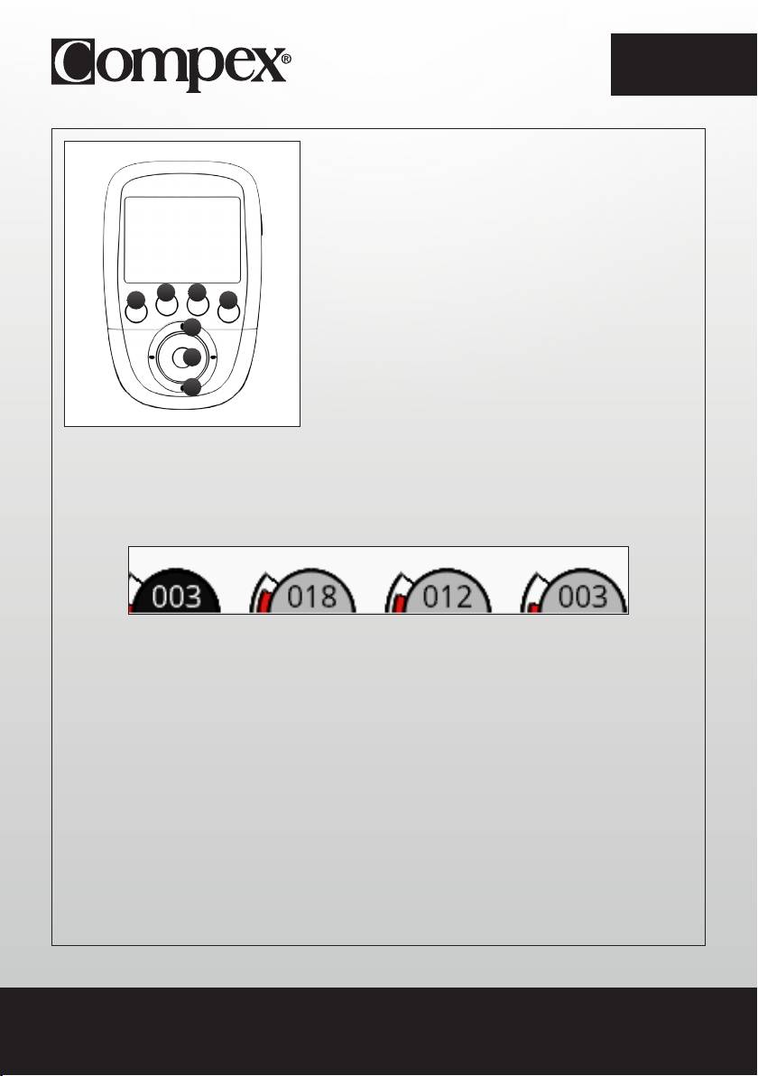
REMOTE CONTROL
A - On/Off button (press briefly to turn on, hold
down for more than 2 sec. to turn off)
B - 4 buttons for the selection/deselection of
A
the stimulation channel
C - Multifunction pad (up-down-left-right) to
navigate the interface and increase or decrease
the level of stimulation intensity of the selected
channels
D - Confirm button
E - Plug for the USB cable or the docking
B
station connector
CD
E
MODULE
A
A - On/Off button (press briefly to turn on, press
and hold down to turn off)
Flashing green LED: Ready
Flashing yellow LED: In stimulation
B - Groove for winding the cable
B
08
EN
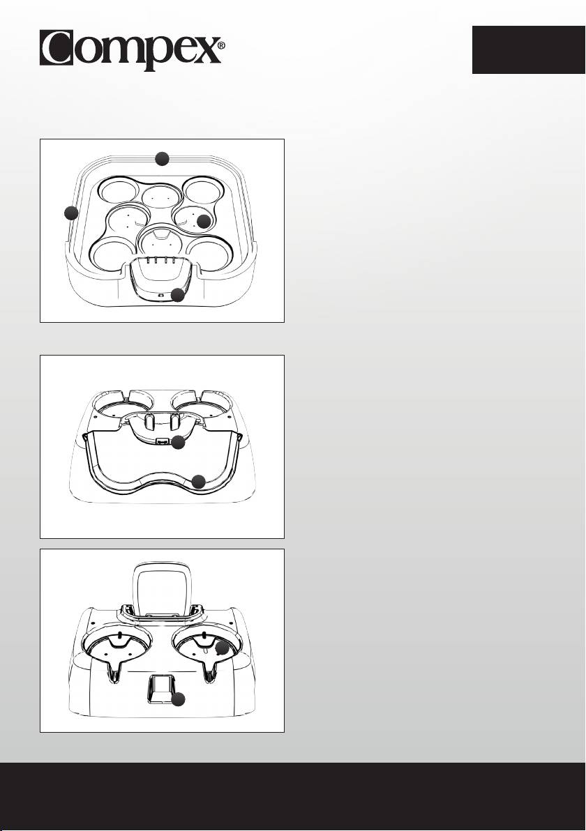
DEVICE DESCRIPTION
SP 6.0 AND 8.0 DOCKING STATION
D
A - Remote control charging connector
B - Notch to open the lid of the docking station
B
C - Location for positioning the modules to
C
be recharged
D - Charger plug
A
FIT 5.0 DOCKING STATION
A - Remote control charging connector
B - Location for positioning the modules
C - Location for positioning the modules to be
A
recharged
D - Charger plug
B
C
D
09
EN
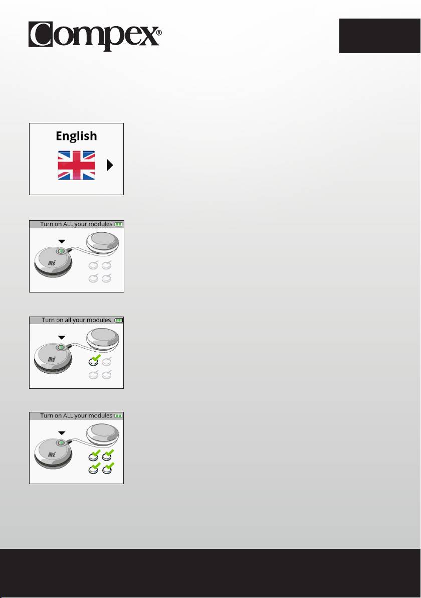
FIRST USE
When using the device for the first time, the following steps must be followed:
1. Select language
2. Turn on all modules in order to pair them with the remote control.
Once a module is turned on and recognized by the remote control, a check appears on the module.
When all modules are paired all check marks appear.
N.B.: This pairing procedure is to be performed only once.
10
EN
DEVICE FUNCTION
N.B.: The following screens are generic examples but they work in the same way regardless of the device
that you have.
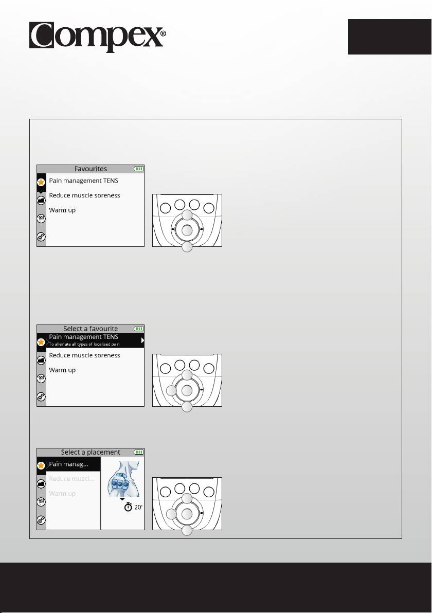
HOW TO ACCESS FAVOURITES
The Favourites menu displays the last programmes done. You need only have one programme in the
Favourites menu to become directly accessible after turning on the device.
A
A Select the Favourites menu
B Confirm your selection
B
A
The programmes done will automatically be placed in the Favourites menu. The Favourites menu can
contain up to 10 programmes. If new programmes are done, the old ones will automatically be removed
from the list of favourites.
1. SELECT A PROGRAMME
A Select the desired favourite programme
A
B Confirm your selection
C
B
C Return to the previous step
A
2. SELECT ELECTRODE PLACEMENT
A Select the desired electrode placement
A
B Confirm your selection
BC
C Return to the previous step
A
11
EN
The placement of electrodes selected during the programme appears. It is possible to scroll through
other electrode placements.
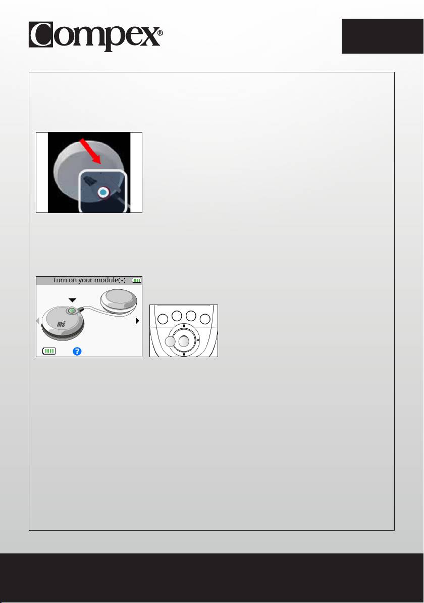
3. CONNECT THE MODULES TO THE ELECTRODES
Stick the electrodes to your skin. The module is attached to the electrode from the side. Slide the module
onto the electrode’s snap until it clips into place.
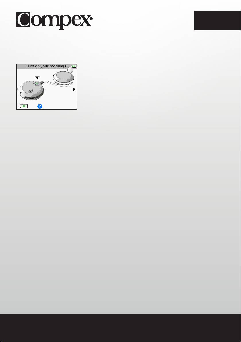
4. TURN ON THE MODULES
A Return to the previous step
B Confirm your selection
BA
To launch the programme, see the section entitled “Start a stimulation programme.”
12
EN
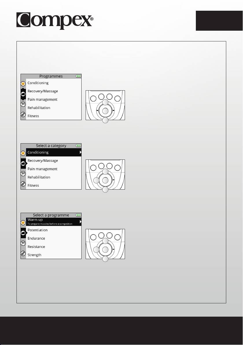
HOW TO ACCESS PROGRAMMES
For more information on programmes, connect to: www.compex.info
The Programmes menu displays the programme categories.
A
A Select the Programmes menu
B Confirm your selection
B
A
1. SELECT A CATEGORY
A Select the desired programme category
A
B Confirm your selection
C
B
C Return to the previous step
A
2. SELECT A PROGRAMME
A Select the desired programme
A
B Confirm your selection
C
B
C Return to the previous step
A
13
EN
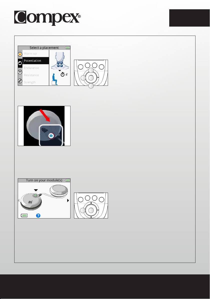
3. SELECT ELECTRODE PLACEMENT
A Select the desired electrode placement
A
B Confirm your selection
C
B
C Return to the previous step
A
4. CONNECT THE MODULES TO THE ELECTRODES
Stick the electrodes to your skin. The module is attached to the electrode from the side. Slide the module
onto the electrode’s snap until it clips into place.
5. TURN ON THE MODULES
A Return to the previous step
B Confirm your selection
BA
To launch the programme, see the section entitled “Start a stimulation programme.”
14
EN
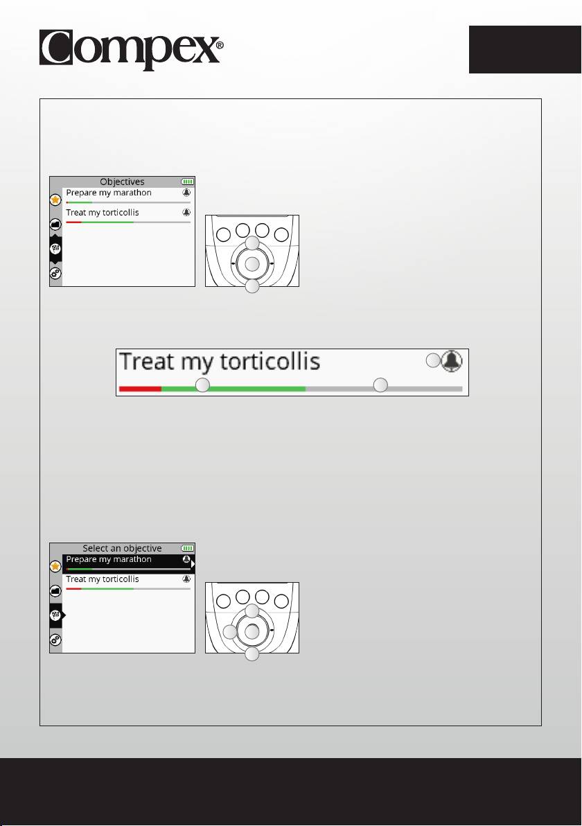
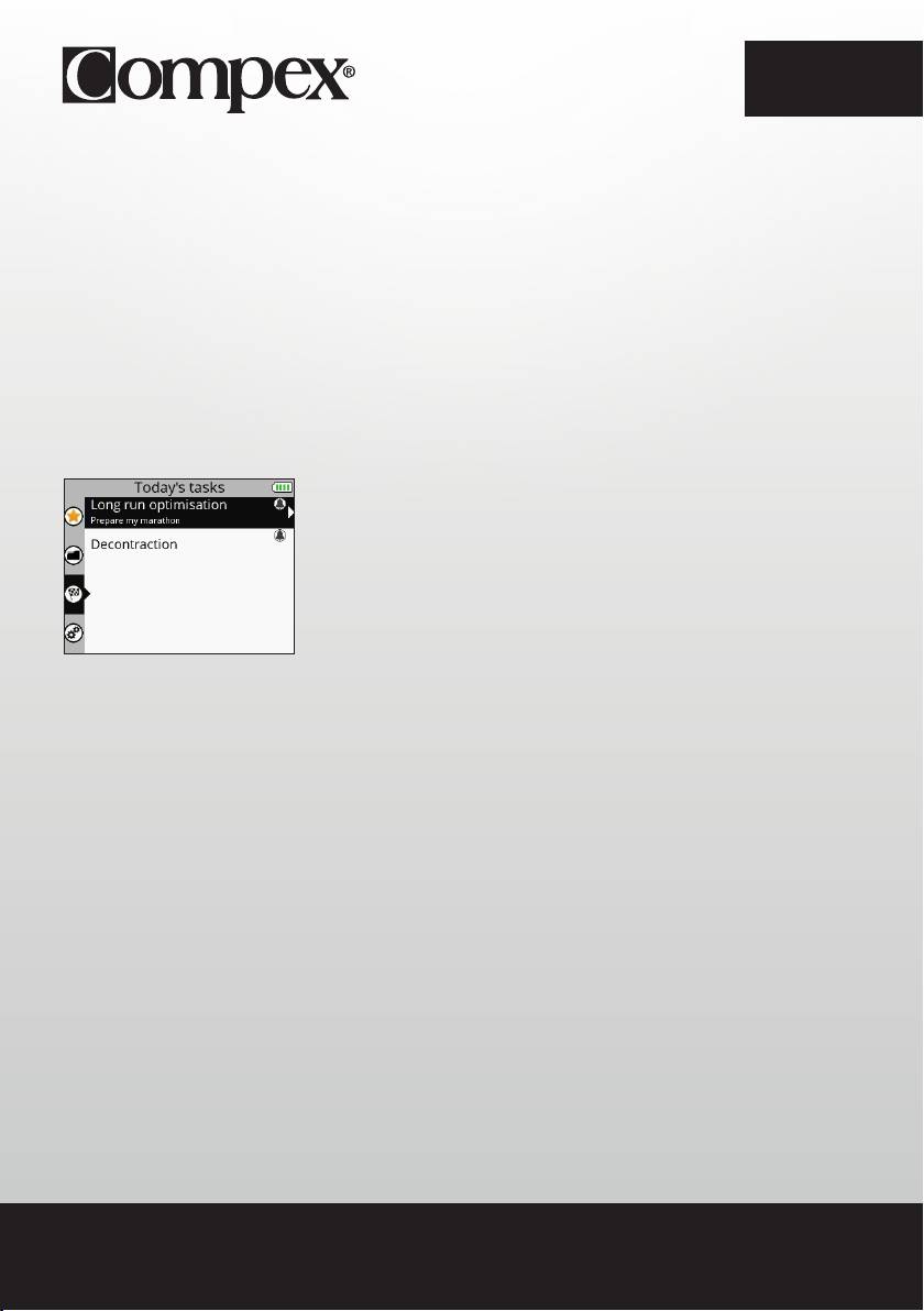
HOW TO ACCESS OBJECTIVES
The Objectives menu displays the objectives downloaded from your personal account (see section
entitled “Creating your personal account”).
N.B.: The Objectives menu is only available for the SP 8.0 device.
A
A Select the Objectives menu
B Confirm your selection
B
A
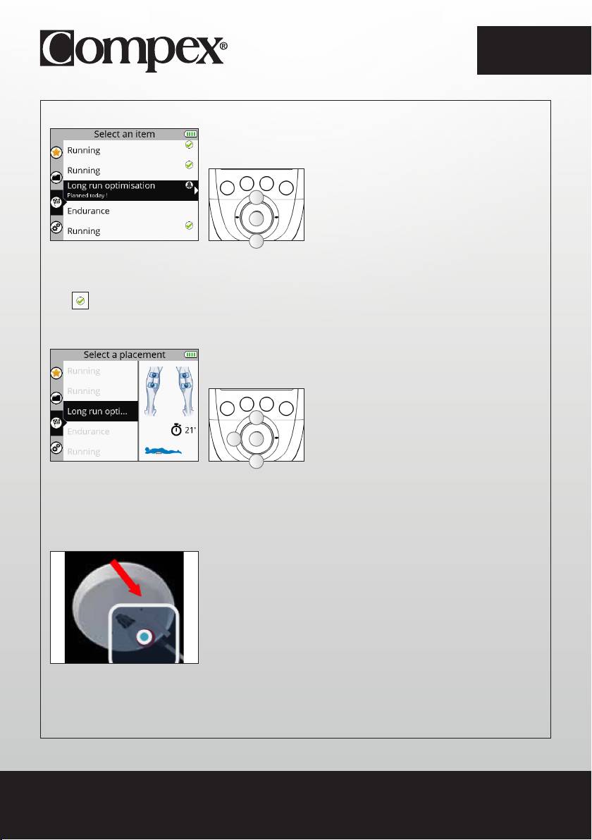
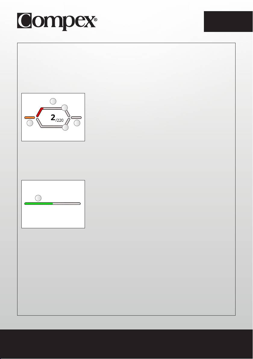
The progress bar under the objective shows the progress of the objective and what remains to be done.
The bell indicates that there is an element of the objective to perform today.
A
BC
A Indicates an element of the objective to perform today
B What remains to be done
C What has already been accomplished:
- What has been completed appears in green
- What has not been completed appears in red
1. SELECT AN OBJECTIVE
A Select the desired objective
A
B Confirm your selection
C
B
C Return to the previous step
A
15
EN
2. SELECT AN ELEMENT TO DO
A Select the desired element
A
B Confirm your selection
B
C Return to the previous step
A
The element to do can be a programme or a task. The element to do is selected by default, but it is
possible to select another.
The next to a programme or a task signifies that it has been done.
3. SELECT ELECTRODE PLACEMENT
A Select the desired electrode placement
A
B Confirm your selection
C
B
C Return to the previous step
A
N.B.: In most cases a different electrode placement cannot be selected because it is directly linked to the
objective.
4. CONNECT THE MODULES TO THE ELECTRODES
Stick the electrodes to your skin. The module is attached to the electrode from the side. Slide the module
onto the electrode’s snap until it clips into place.
16
EN
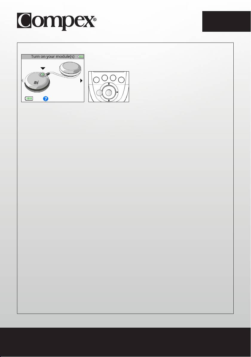
5. TURN ON THE MODULES
A Return to the previous step
B Confirm your selection
BA
To launch the programme, see the section entitled “Start a stimulation programme.”
17
EN
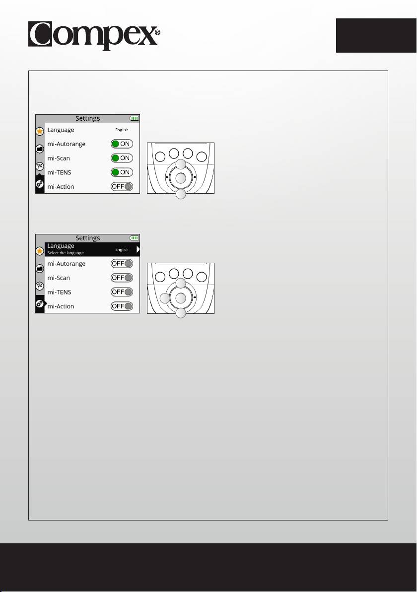
HOW TO ACCESS SETTINGS
The Settings menu enables certain elements to be configured such as backlighting, volume, language,
etc. Some settings are not available in all devices.
A
A Select the Settings menu
B Confirm your selection
B
A
1. SELECT A SETTING
A Select the desired setting
A
B Confirm your selection
BC
C Return to the previous step
A
Language: Allows you to change the device’s language
MI-autorange: Turns the MI-autorange function on (ON) or off (OFF)
MI-range: Turns the MI-range function on (ON) or off (OFF)
MI-scan: Turns the MI-scan function on (ON) or off (OFF)
MI-tens: Turns the MI-tens function on (ON) or off (OFF)
MI-action: Turns the MI-action function on (ON) or off (OFF)
N.B.: For an explanation of MI functions see the section entitled “3. How does MI technology work?”.
18

EN
Cycles: Turns the Cycles function on (ON) or off (OFF)
The Cycles function is for people who are already accustomed to electrostimulation and want to perform
several training cycles. If the Cycles function is turned on (ON) an additional screen will appear for certain
programmes (programmes inducing powerful muscle contractions) enabling the training cycle to be
selected.
The cycle logic refers to the workload performed by electrostimulation. And just like a normal workout,
one has to to start with an amount of work then increase it over the course of the cycles. Thus, it is
recommended starting with the 1st cycle and going on to the next level when the cycle is finished,
normally after 4 to 6 weeks of stimulation based on 3 sessions per week. It is also important to have
reached significant stimulation intensities in sessions before going on to another cycle.
Power saving: Turns the Power saving function on (ON) or off (OFF). Decreases the intensity and the
backlighting time.
Sound: Turns the Sound function on (ON) or off (OFF).
Contraction sound: Turns the contraction arrival warning sound on (ON) or off (OFF).
Set time: Allows you to set the time on the device.
Set date: Allows you to set the date on the device.
Pair a new module: Enables a new module to be paired to the remote control.
Reset the device: Enables the device to be re-set and return to the basic settings (Favourites deleted,
Objectives cleared, Default settings).
System info: Enables information related to the device to be viewed.
19
EN
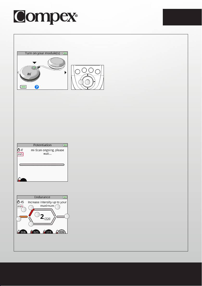
START A STIMULATION PROGRAMME
Before beginning any stimulation programme, you must turn the modules on.
A Return to the previous step
B Confirm your selection and start the
A B
programme
To turn on the modules, press their respective On/Off button. As soon as the module is turned on, its
battery level appears on the screen. Turn on the number of modules desired according to the electrode
placement selected. As soon as a sufficient number of modules is turned on, a small arrow appears on
the right of the screen.
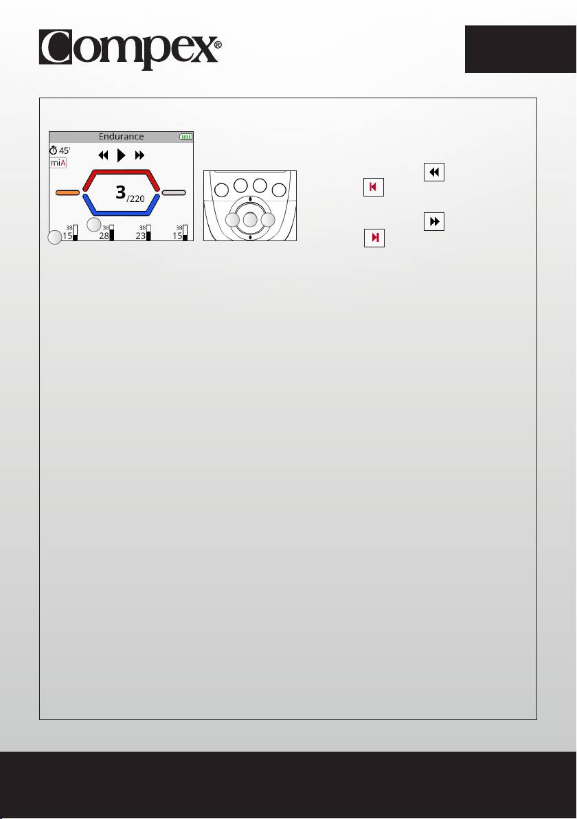
If the MI-scan function is activated, the programme starts with a short sequence during which
measurements are taken. For the duration of the measurement test, it is important to stand still and be
perfectly relaxed. Once the test is completed, the programme can start. Stimulation always starts at 000.
A Contraction phase
B Warm up phase
A
G
F
C Active rest phase
E
D Relaxation phase
D
B
E Number of contractions performed / Total number of contractions
C
F Indication of the active MI function
G Pop-up help indicating information or actions to be taken
20
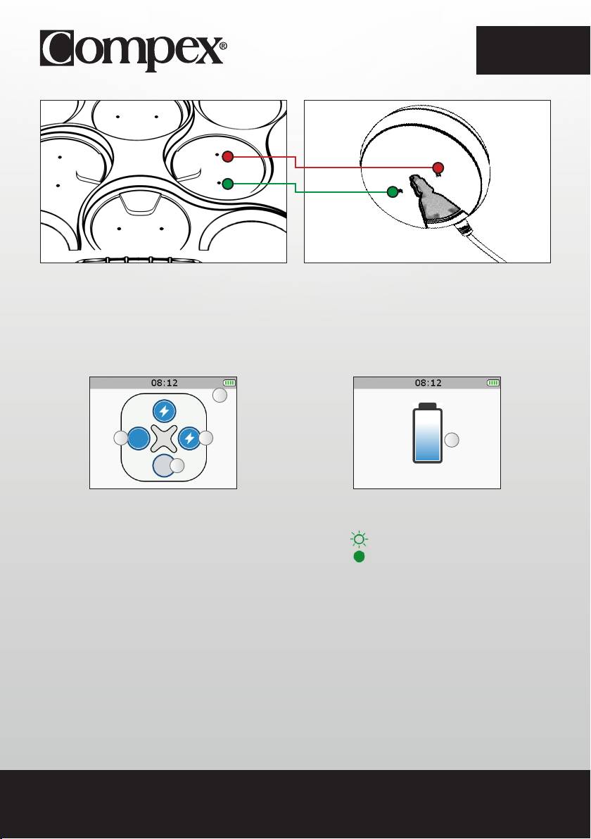
EN
A Select the channels on which to act. When a channel is
active the LED button emits a strong blue light.
B Pause
A A
A
A
C Increase or decrease the stimulation intensities on the
C
selected channels
B
C
Increase the stimulation intensities on the selected channels.
By default, all of the channels are active at the beginning of the session. To deselect a channel, simply
press the corresponding button.
In this case only channel 1 is active. Any change of intensity will only be performed on channel 1.
21
EN
Depending on the programme, the diagram on the middle of the screen can change.
CONTRACTION/ACTIVE REST PROGRAMME
These programmes always begin with a warm-up phase. After this warm-up phase, a contraction cycles
phase followed by active rest occurs (the number of cycles depends on the programme) and when all
cycles are completed, the programme ends with a relaxation phase.
E
A Warm up phase
D
B Active rest phase
C Relaxation phase
A
C
D Contraction phase
B
E Work phase which consists of a contraction/active rest cycle
MASSAGE, RECOVERY TYPE PROGRAMME
These programmes consist of a single phase and have no contraction/active rest cycle. These are
recovery, massage, capillarisation, or even pain type programmes. During this type of programme,
frequency variations can occur.
A
A Work phase
22
EN
CONTINUE A STIMULATION PROGRAMME
A Skip the current phase or exit the
programme
B Resume the stimulation session
CBA
C Skip the current phase or exit the
B
A
programme
A Average stimulation intensity
B Maximum stimulation intensity
By pressing on the central button of the remote control or on the On/Off button of one of the modules
during the stimulation, the device goes into pause. At this point it is possible to skip the current phase or
exit the programme.
Depending on the programme, maximum and average intensities statistics may appear.
N.B.: The session restarts with intensities equal to 80% of those used prior to the interruption.
23
EN
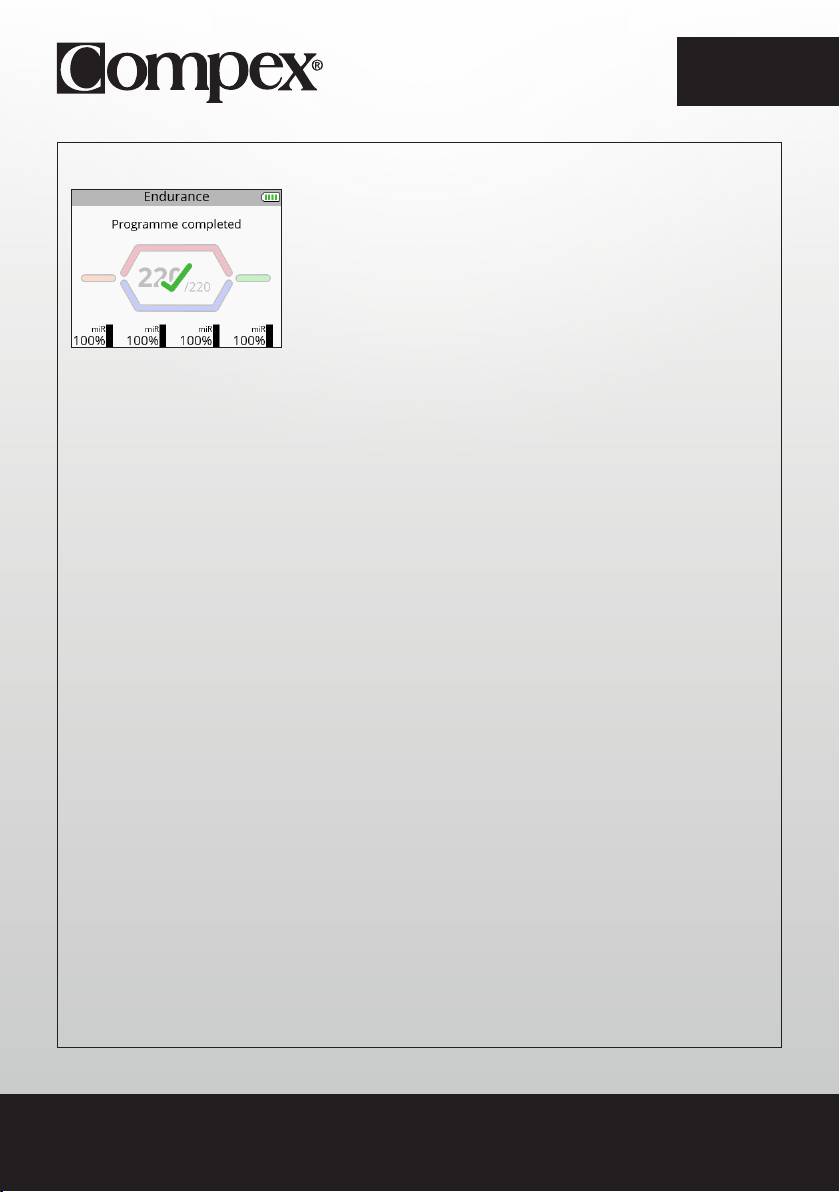
END A STIMULATION PROGRAMME
At the end of the session a screen with a check mark appears. Pressing on any button returns you to
the Favourites menu. To turn off the device, hold down the remote control’s On/Off button for 2 seconds.
This will also result in turning off all modules.
Depending on the programme, maximum and average intensities statistics may appear.
24
EN
CHARGING
BATTERY LEVEL INDICATION
B
A Module battery level
B Remote control battery level
A
Module battery levels appear just prior to launching the stimulation session. The remote control battery level is
always visible in the top right corner.
CONNECT THE DOCKING STATION
Connect the AC adapter supplied with your device to the docking station and then plug it into a power outlet.
It is strongly recommended that you fully charge the remote control batteries and modules before first use in
order to improve its performance and life expectancy.
25
EN
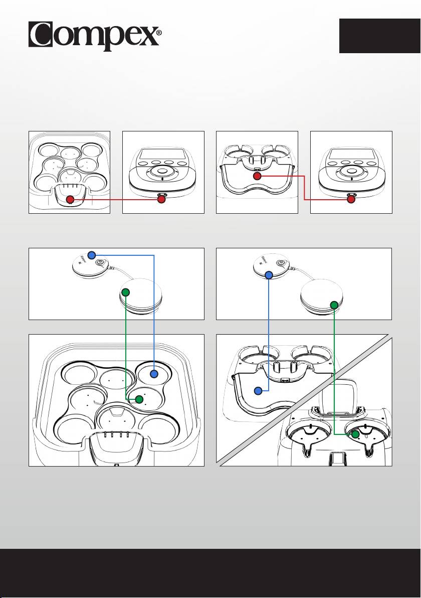
CHARGE THE REMOTE CONTROL AND THE MODULES
At the end of the stimulation session, it is strongly recommended that you store the remote control and
modules in the docking station to charge the elements.
SP 6.0, 8.0 FIT 5.0
In order to do so, place the remote control on its connector.
Then place the modules in the slots provided for this purpose.
To do so, place the pod without the On/Off button (the green one in the figure) in the location indicated in
green and the other pod in the location indicated in blue. Do the same for the other modules.
26
EN
The pod without the On/Off button must fit on the small connectors. A magnet as well as the small vertical
mark on the hull of the pod helps to position the pod correctly in its slot. When it is positioned correctly you
should hear a click.
SP 6.0, 8.0 FIT 5.0
A
BC
A
D
A Remote control battery charging
A Remote control battery charging
B Module charging
LED flashing: Module charging
C Module charged
LED full: Module charged
D No module present
When a module is placed on the docking station it
When a module is placed on the docking station,
appears on the remote control’s screen.
the green LED indicates the module’s status.
As soon as the remote control and modules are
As soon as the remote control and modules are
fully charged, they go into standby mode.
fully charged, they go into standby mode.
N.B.: If the device is not used for an extended period, we recommend that you charge the batteries to 50%
of their capacity every 3 months.
27
EN
CREATE YOUR PERSONAL ACCOUNT
To take advantage of all of your device’s capabilities you must first create an account at the following address
www.compexwireless.com and follow the instructions on the website.
Functions associated with the SP 8.0
• Access a training schedule
• Download preset objectives directly into the device
• Create your own objectives and download them directly into the device
• Upload the device’s history (stimulation programmes done) to the website
As soon as an objective is downloaded into the remote control, the first screen that appears when the device
is switched on displays the daily tasks to be performed.
Functions associated with the SP 6.0 and FIT 5.0
• Access a training schedule
• Upload the device’s history (stimulation programmes done) to the website
28
EN
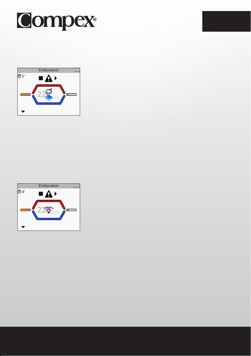
5. TROUBLESHOOTING
ELECTRODE FAULT
The remote control displays the symbol of an electrode and a disconnected module and an arrow flashes on
the channel in question (in this case, channel 1).
• Ensure that the electrodes are properly connected to the module.
• Check to see if electrodes are old, worn and/or if contact is poor: try using new electrodes.
MODULE OUT OF RANGE
The remote control displays the out of range symbol and an arrow flashing on the channel where the problem
was detected (in this case, channel 1).
• Check to make sure that the module and the remote control are less than 2 metres away from each other.
• Make sure you are not in an isolated area with no obstacle to reflect the signal from the remote control.
• Make sure you are in an area that enables the signal to be reflected from the remote control.
29

EN
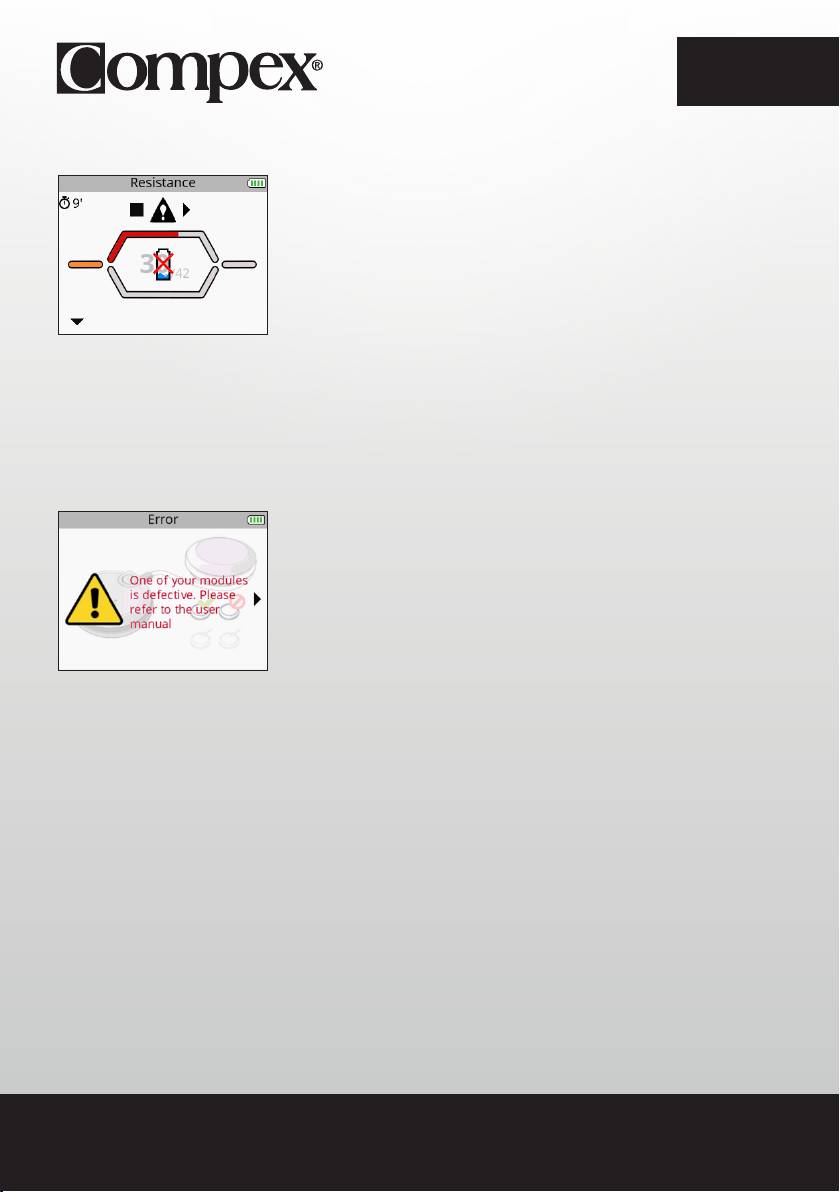
SYNCHRONIZATION PROBLEM
If the synchronization process was discontinued or cannot run successfully for any reason (remote control
disconnected, power failure, etc.) the remote control may, in some cases, display this screen.
• Reconnect the remote control to the computer and restart the synchronization process.
BEHAVIOUR OF THE MODULE’S LED
The LED alternately flashes green and red: the module is out of range or not recognized by the remote
control.
• Ensure the remote control is on.
• Ensure that the module and the remote control are less than 2 metres away from each other.
The LED is still red.
• Ensure the module is charged.
• Try to restart the remote control and modules.
• If despite this the LED is still red, contact customer service provided and approved by Compex.
The LED does not turn on.
• Ensure the module is charged.
• If despite this the LED still does not turn on, contact customer service provided and approved by Compex.
30
EN
MODULE UNCHARGED
During the stimulation a module may be uncharged. In this case the symbol for an uncharged battery
appears and an arrow flashing on the channel where the problem was detected (in this case, channel 1).
• Stop the stimulation and recharge the uncharged module.
• Abandon the uncharged module and continue the stimulation session without it.
THE MODULE WILL NOT PAIR WITH THE REMOTE CONTROL
At the time of first use, if the remote control is unable to pair all modules, an error message may appear.
• Ensure that the module is charged, and repeat the pairing step.
• If despite this the message returns, contact customer service provided and approved by Compex.
STIMULATION DOES NOT PRODUCE THE USUAL SENSATION
• Check that all settings are right and check electrodes are properly positioned.
• Change the positioning of the electrodes slightly.
STIMULATION CAUSES DISCOMFORT
• Electrodes lose their adhesive capacity and no longer provide adequate contact with skin.
• Electrodes are worn and must be replaced.
• Change the positioning of the electrodes slightly.
31

EN
THE DEVICE IS NOT WORKING
• Ensure that the remote control and modules are charged.
• Try to restart the remote control and modules.
• If despite this the device still does not work, contact customer service provided and approved by Compex.
32

EN
6. DEVICE MAINTENANCE
GUARANTEE
See the attached leaflet.
MAINTENANCE
Your stimulator does not require any calibration or periodic maintenance. Use a soft cloth and solvent-free
alcohol-based detergent to clean your device. Use as little liquid as possible to clean the device. Do not
dismantle the stimulator or the charger because they contain high voltage components which could cause
electrocution. This must be carried out by Compex-approved technicians or repair services. If your stimulator
contains parts that appear to be worn or faulty, please contact the closest Compex customer service centre.
STORAGE/TRANSPORT AND USE
STORAGE AND TRANSPORT USE
TEMPERATURE -20° C to 45° C 0° C to 40° C
MAXIMUM RELATIVE HUMIDITY 75% 30% to 75%
ATMOSPHERIC PRESSURE from 700 hPa to 1060 hPa from 700 hPa to 1060 hPa
Do not use in areas at risk of explosion.
DISPOSAL
Batteries must be disposed of in accordance with national current regulations. Any product bearing the
WEEE label (a bin crossed out with a cross) must be separated from household waste and sent to special
recycling plants.
33

EN
7. TECHNICAL SPECIFICATIONS
GENERAL INFORMATION
Remote control battery: Rechargeable 3.7[V] / ≥ 1,500[mAh] lithium polymer (LiPo) battery.
Module battery: Rechargeable 3.7[V] / ≥ 450[mAh] lithium polymer (LiPo) battery.
SP 6.0 and 8.0 AC power adapter: Only 5[V] / 3.5 [A] AC power adapters bearing reference number 64902X
can be used to recharge your device.
FIT 5.0 AC power adapter: Only 5[V] / 1.5 [A] AC power adapters bearing reference number 00108X can be
used to recharge your device.
Product and accessories expected service life: 5 years
Electrode shelf life: refer to electrodes bag
NEUROSTIMULATION
All the electrical specifications are supplied for an impedance from 500 to 1000 ohms per channel.
Outputs: four independent and individually adjustable channels, electrically insulated from one another.
Impulsion form: constant rectangular current with compensated impulses to eliminate any direct element of
continuous current to avoid any residual polarisation from the skin.
Maximum impulse intensity: 120 mA.
Impulse intensity increments: manual adjustment of stimulation intensity from 0 to 999 (energy) by minimum
increments of 0.25 mA.
Duration of impulses: from 50 to 400 μs.
Maximum quantity of electricity per impulse: 96 microcoulombs (2 x 48 μC, compensated).
Typical impulse rise time: 3 μs (20%-80% of maximum current).
Frequency of impulses: 1 to 150 Hz.
34

EN
RF DATA
Transmission frequency band: 2.4[GHz] ISM
The characteristics of the type and frequency of modulation: GFSK, +/-320[kHz] deviation
Effective emission power: 4.4 [dBm]
STANDARDS
To ensure your safety, the stimulator has been designed, manufactured and distributed in accordance with
the requirements of the amended European Directive 93/42/CEE covering medical devices.
The stimulator also complies with the CEI 60601-1 standard covering general safety requirements for
electromedical devices, with the CEI 60601-1-2 standard covering electromagnetic compatibility and the CEI
60601-2-10 standard covering special safety requirements for nerve and muscle stimulators
In accordance with current international standards, a warning must be given about applying electrodes to the
thorax (increased risk of cardiac fibrillation).
The stimulator also complies with Directive 2002/96/CEE covering electrical equipment and electronic waste
(WEEE).
INFORMATION ABOUT ELECTROMAGNETIC COMPATIBILITY (EMC)
The Compex is designed to be used in typical domestic approved environments in accordance with the
safety standard EMC EN 60601-1-2.
This device emits very low levels in the radiofrequency interval (RF) and is therefore not likely to cause
interference with electronic equipment nearby (radios, computers, telephones, etc.).
The Compex is designed to support anticipated disturbance originating from electrostatic discharge,
magnetic fields for the power supply or radiofrequency emitters.
However, it is not possible to guarantee that the stimulator will not be affected by powerful RF fields
(radiofrequency) originating from other sources.
For more information about electromagnetic emission and immunity, please contact Compex.
35

EN
8. EMC TABLE
The Compex Stimulator requires special precautions regarding EMC and needs to be installed and put into
service according to the information provided on the EMC in this manual.
All RF wireless transmission devices can affect the Compex Stimulator. The use of accessories, sensors,
and cables other than those specified by the manufacturer, may result in greater emissions or reduce the
immunity of the Compex Stimulator.
The Compex Stimulator should not be used beside or stacked on other equipment, if adjacent or stacked
use is necessary, one must check the correct functioning of the Compex Stimulator within the context of the
configuration used.
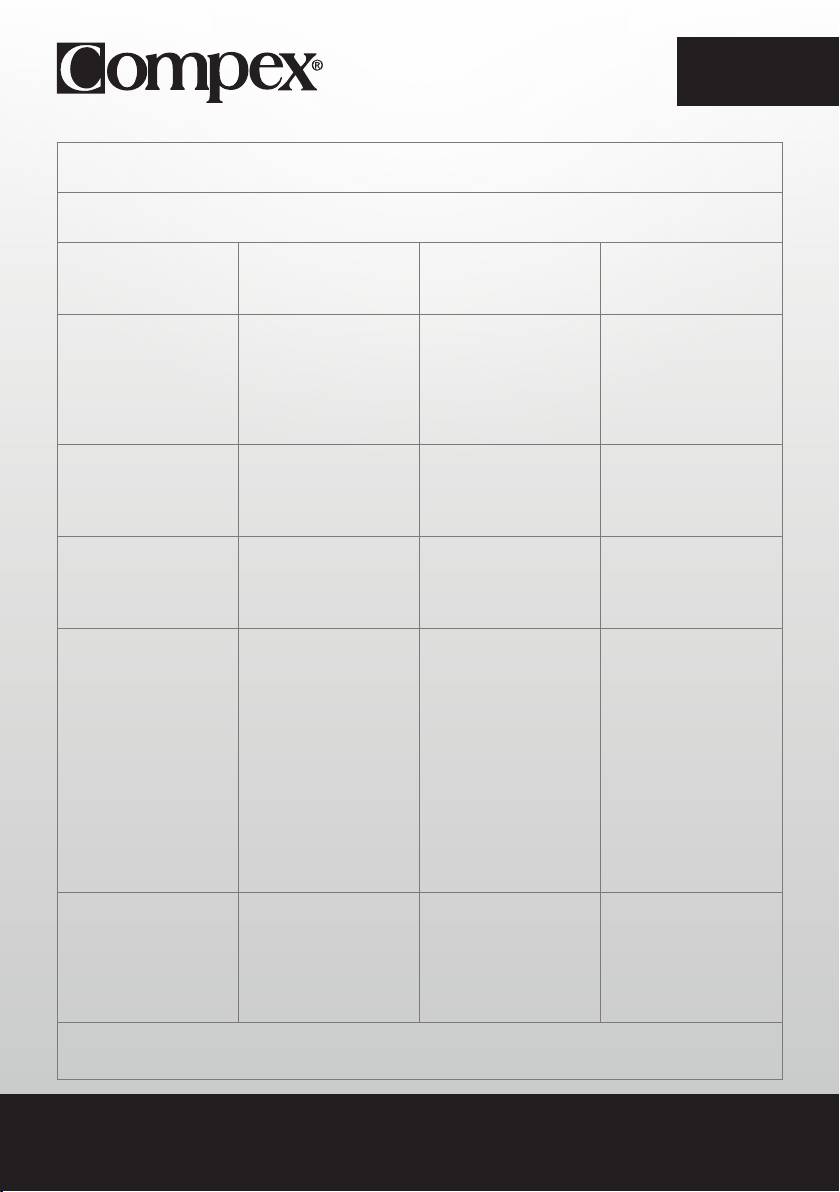
RECOMMENDATIONS AND DECLARATION BY THE
MANUFACTURER CONCERNING ELECTROMAGNETIC EMISSIONS
The Compex Stimulator is intended for use in the electromagnetic environment specified below.
The customer or user of the Compex Stimulator should ensure that it is used in this environment
ELECTROMAGNETIC ENVIRONMENT
EMISSIONS TEST COMPLIANCE
- GUIDE
The Compex Stimulator uses RF
energy only for its internal operation.
RF emissions
Consequently, its RF emissions are
Group 1
CISPR 11
unlikely to interfere with any adjacent
electrical device (radios, computers,
telephones etc.).
RF emissions
Class B
CISPR 11
Compex Stimulator is suitable for use in
any establishment, other than a private
Harmonic emissions
Class A
dwelling or a place connected directly
IEC 61000-3-2
to the low voltage mains supply which
Voltage fluctuations/ emission
powers residential buildings.
Not applicable
oscillations IEC 61000-3-3
36
EN
RECOMMENDATIONS AND DECLARATION BY THE MANUFACTURER CONCERNING
ELECTROMAGNETIC IMMUNITY
Compex Stimulator is designed for use in the electromagnetic environment stipulated below. The buyer or user of the
Compex Stimulator must ensure it is used in this recommended environment.
ELECTROMAGNETIC
IMMUNITY TEST TEST LEVEL IEC 60601 OBSERVANCE LEVEL
ENVIRONMENT -
RECOMMENDATIONS
Floors must be wood,
concrete or ceramic tile.
±6 kV at the contact
Electrostatic discharge (DES)
±6 kV at the contact
If floors are covered with
CEI 61000-4-2
±8 kV in air
synthetic material the relative
±8 kV in air
humidity must be maintained
at a minimum of 30%.
±2 kV for power supply lines
The quality of the electrical
Fast transient electrical
±2 kV for power supply lines
power supply should be that
bursts
Not Applicable for input/
of a typical commercial or
CEI 61000-4-4
±1 kV for input/output lines
output lines
hospital environment.
The quality of the power
±1 kV differential mode
±1 kV differential mode
Surge
supply should be that of
CEI 61000-4-5
a typical commercial or
N/A
±2 kV joint mode
hospital environment.
<5 % VT (dips >95 % de UT)
<5 % VT (dips >95 % de UT)
for 0.5 cycle
for 0.5 cycle
The quality of the power
supply should be that of
<40 % VT
<40 % VT
a typical commercial or
Voltage dips, short
(dips >60 % de UT)
(dips >60 % de UT)
hospital environment. If the
interruptions and voltage
for 5 cycles
for 5 cycles
Compex Stimulator user
variations on power supply
requires continuous operation
lines
<70 % VT
<70 % VT
during mains power cuts, it is
CEI 61000-4-11
(dips >30 % de UT)
(dips >30 % de UT)
recommend that the Compex
for 25 cycles
for 25 cycles
Stimulator is powered by a
UPS or a battery.
<5 % VT (dips >95 % de UT)
<5 % VT (dips >95 % de UT)
for 5 seconds
for 5 seconds
Magnetic fields at the mains
frequency should be at a
Magnetic field at grid
level characteristic of a
frequency (50/60 Hz)
3 A/m 3 A/m
typical location in a typical
CEI 61000-4-8
commercial or hospital
environment.
NOTE :VT is the AC supply voltage before application of the test level.
37
EN
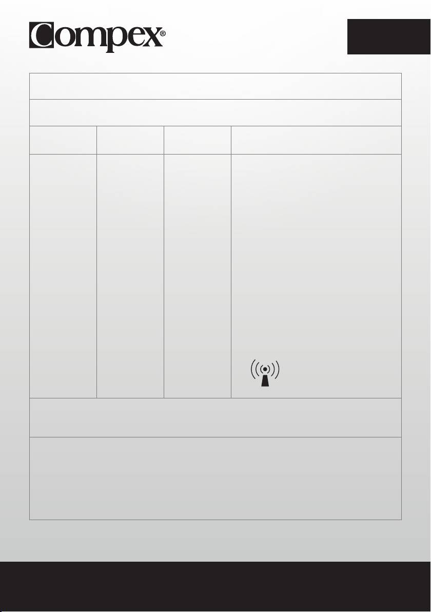
RECOMMENDATIONS AND DECLARATION BY THE MANUFACTURER
CONCERNING ELECTROMAGNETIC IMMUNITY
Compex Stimulator is designed for use in the electromagnetic environment stipulated below. The buyer or user of the
Compex Stimulator must ensure it is used in this recommended environment.
TEST LEVEL IEC
OBSERVANCE
ELECTROMAGNETIC ENVIRONMENT -
IMMUNITY TEST
60601
LEVEL
RECOMMENDATIONS
Portable and mobile RF communication devices must
only be used relative to the Compex Stimulator and its
wiring at a distance which is not less than the spacing
recommended and calculated using the appropriate
equation for the transmitter’s frequency.
Recommended spacing
d = 1.2 √P
Conducted RF IEC
d = 1.2 √P 80 MHz to 800 MHz
61000-4-6
3 Vrms
d = 2.3 √P 800 MHz to 2.5 GHz
150 kHz to 80 MHz
3 Vrms
where P is the maximum output power of the transmitter
Radiated RF
in watts (W) set by the manufacturer’s specifications and
3 V/m
3 V/m
IEC
where d is the recommended spacing in metres (m).
80 MHz to 2.5 GHz
61000-4-3
The field intensity of RF fixed transmitters, as determined
by an electromagnetic survey a must be less than the
observance level to be found in each frequency rangeb.
Interference may occur close to any appliance identified
by the following symbol:
NOTE 1 At 80 MHz and at 800 MHz ,the high frequency amplitude is applied
NOTE 2 These guidelines may not be appropriate for some situations. Electromagnetic wave propagation
is modified by absorption and reflection due to buildings, objects and persons.
a The field intensity from fixed transmitters, such as radio telephone base stations (cellular/wireless) and a mobile radio, amateur
radios, AM and FM radio transmissions and TV transmissions cannot be predicted with any accuracy. It may therefore be necessary
to consider an analysis of the electromagnetic environment of the site to calculate the electromagnetic environment coming from
fixed RF transmitters. If the field intensity measured in the environment where the Compex Stimulator is located exceeds the
appropriate RF observance level above, the Compex Stimulator should be monitored to ensure it is operating properly. In the event
of abnormal operation, new measures may then be imposed, such as realignment or movement of the Compex Stimulator.
b Above the frequency amplitude from 150 kHz to 80 MHz, the field intensity must be < 3 V/m.
38
20xx
LATEX
REF
FREE

EN
RECOMMENDED SPACING BETWEEN A PORTABLE AND MOBILE COMMUNICATION DEVICE
AND THE COMPEX STIMULATOR
The Compex Stimulator is designed for use in an electromagnetic environment in which radiated RF waves are controlled.
The buyer or user of the Compex Stimulator can contribute to preventing electromagnetic interference by maintaining a
minimum distance between portable and mobile RF communication devices (transmitters) and the Compex Stimulator
according to the table of recommendations below and according to the maximum output power of the telecommunication
device.
SPACING ACCORDING TO THE FREQUENCY OF THE TRANSMITTER M
MAXIMUM TRANSMITTER OUTPUT
FROM 150 KHZ
FROM 80 KHZ
FROM 800 MHZ
POWER W
TO 80 MHZ
TO 800 MHZ
TO 2.5 GHZ
D = 1.2 √P
D = 1.2 √P
D = 2.3 √P
0.01 0.12 0.12 0.23
0.1 0.38 0.38 0.73
1 1.2 1.2 2.3
10 3.8 3.8 7.3
100 12 12 23
In the case of transmitters whose maximum output power is not shown in the table above, the recommended spacing of d in
metres (m) can be calculated using the appropriate equation for the transmitter frequency, where P is the maximum output power
of the transmitter in watts (W) as set by the transmitter manufacturer
NOTE 1 At 80 MHz and at 800 MHz ,the spacing for high frequency amplitude is applied.
NOTE 2 These guidelines may not be appropriate for some situations. Electromagnetic wave propagation is modified by absorption
and reflection due to buildings, objects and persons.
39
