ABUS TVIP61500 Operating instructions – page 4
Manual for ABUS TVIP61500 Operating instructions
Table of contents
- User manual
61
English
8. Inital start-up
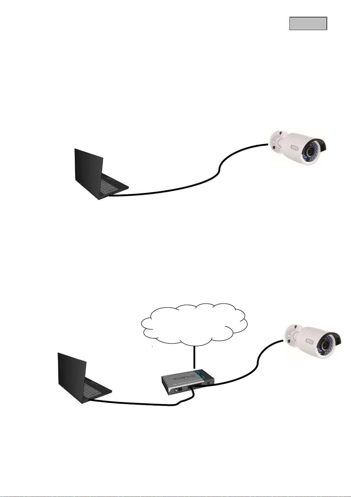
The network camera automatically detects whether a direct connection between the PC and camera
should be made. A crossover network cable is not required for this.
Direct connection of the network camera to a PC/laptop
1. Ensure that a CAT 5 network cable is used.
2. Connect the cable to the Ethernet interface of the PC/laptop and the network camera.
3. Connect the power supply to the network camera.
4. Configure the network interface of your PC/laptop to the IP address 192.168.0.2 default
gateway to 192.168.0.1
5. Go to 8, to finish the initial set-up and establish the connection to the network camera.
Connecting the network camera to a router/switch
1. Ensure that a CAT 5 network cable is used.
2. Connect the PC/laptop to the router/switch.
3. Connect the network camera to the router/switch.
4. Connect the power supply to the network camera.
5. If a DHCP server is available in your network, set the network interface of your PC/laptop to
“Obtain an IP address automatically”.
6. If no DHCP server is available, configure the network interface of your PC/laptop to
192.168.0.2 and the default gateway to 192.168.0.1
7. Go to point 8 to finish the initial set-up and establish the connection to the network camera.
62
English
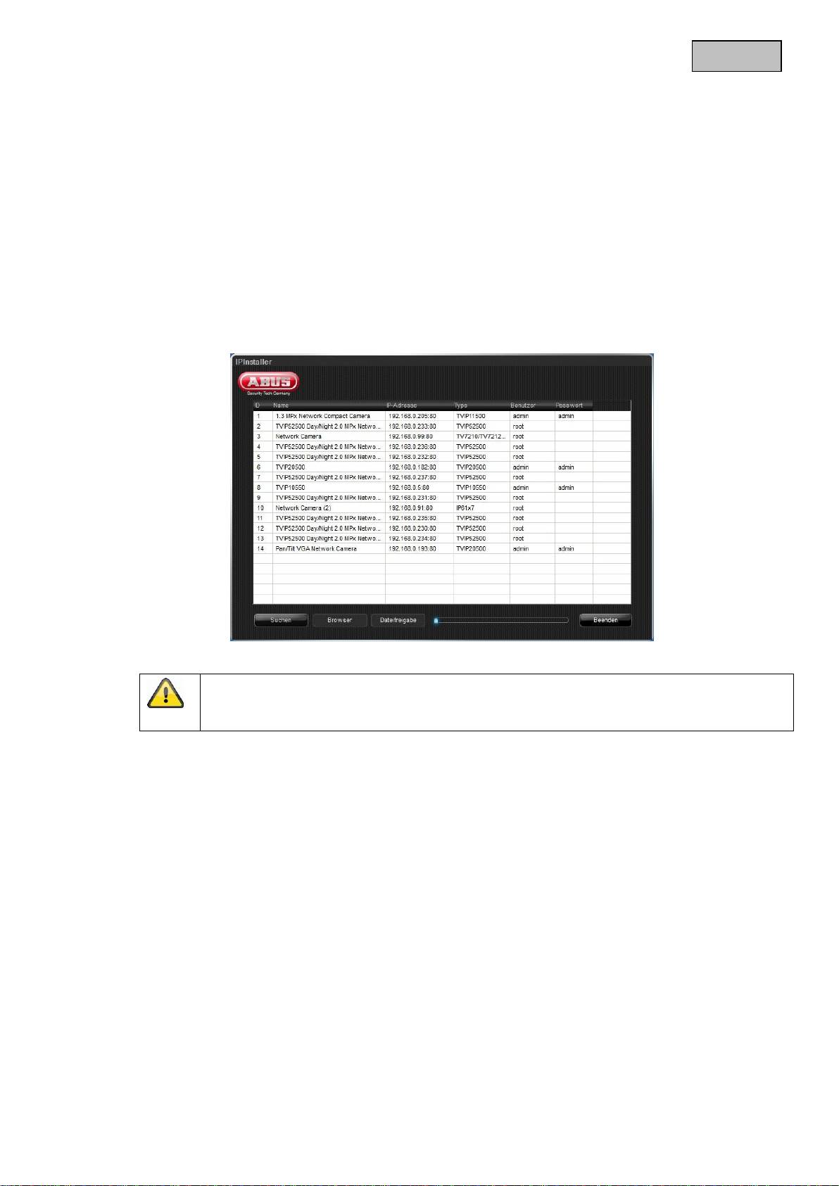
9. Accessing the network camera for the first time
The network camera is accessed for the first time using the IP Installer.
After the installation wizard is started, it searches for all connected ABUS network cameras and video
servers in your network.
You can find the program on the included CD-ROM. Install the program on your PC and then run it.
If a DHCP server is available in your network, the IP address is assigned automatically for both the
PC/laptop and the network camera.
If no DHCP server is available, the network camera automatically sets the following IP address:
192.168.0.100.
Your PC system must be located in the same IP subnetwork in order to establish communication with
the network camera (PC IP address: e.g. 192.168.0.2).
The standard setting for the network camera is “DHCP”. If no DHCP server is in operation in
your network, then we recommend setting the IP address manually to a fixed value following
initial access to the network camera.

63
English
10. Password prompt
When delivered, an administrator password is already defined for the network camera. However, the
administrator should define a new password immediately for security reasons. After the new
administrator password is stored, the network camera asks for the user name and password every
time it is accessed.
The administrator account is set up in the factory as follows: User name “admin” and password
“12345”. Each time the network camera is accessed, the browser displays an authentication window
and asks for the user name and password. Should your individual settings for the administrator
account no longer be accessible, please contact our technical support team.
To enter a user name and password, proceed as follows:
Open Internet Explorer and enter the IP address for the camera (e.g. “http://192.168.0.100”).
You are then prompted for authentication:
-> You are now connected with the network camera and can see a video stream.
64
English
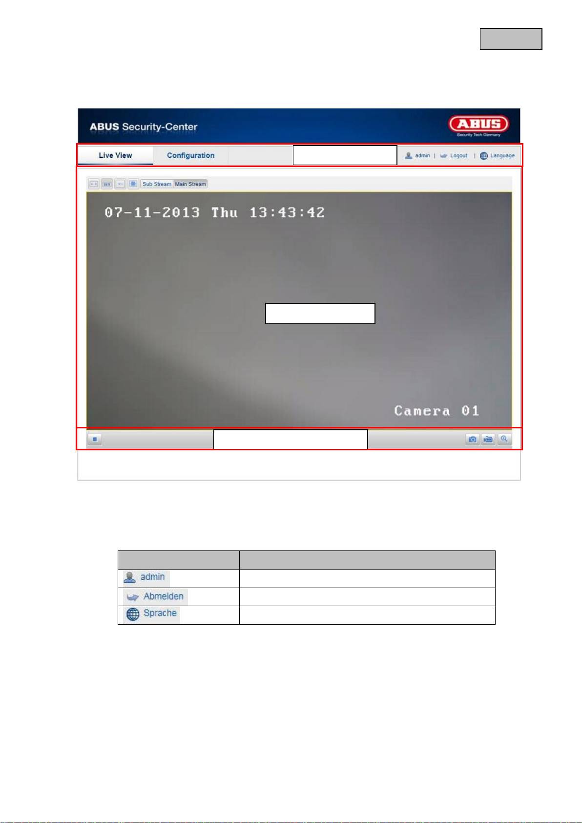
11. User functions
Open the main menu on the network camera. The interface is divided into the following main areas:
11.1 Menu bar
Select the appropriate tab: “Live View”, “Configuration” or “Log”.
Button
Description
Display of the user logged on
User logout
Selection of the desired language
Live image display
Menu bar
Audio / video control
65
English
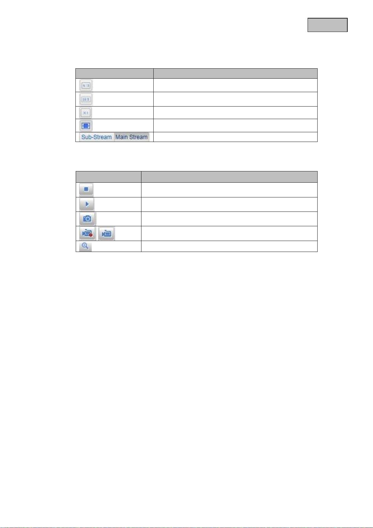
11.2 Live image display
You can access the full-screen view by double-clicking here.
Button
Description
Activate 4:3 view
Activate 16:9 view
Display original size
Adjust view to browser automatically
Selection of the streaming type for the live cast
11.3 Video control
Button
Description
Deactivate live cast
Activate live cast
Instant image (snapshot)
Start / stop manual recording
Start / stop zoom
66
English
12. Configuration
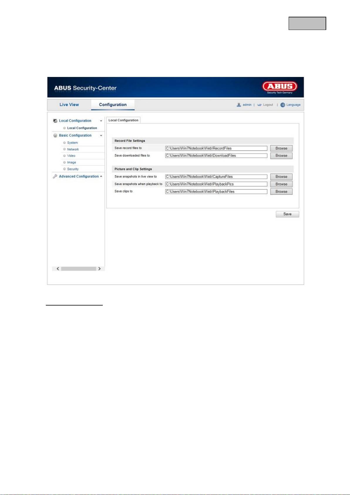
12.1 Local configuration
Under the “Local Configuration” menu item, you can make settings for the live view, file paths of the
recordings and snapshots.
Record File Settings
You can define the recording path and the path for downloaded files here. To apply the changes, click
“Save”.
Save record files to
You can determine the file path that is to be used to manual recordings here.
The default path is C:\\<User>\<Computer_Name>\Web\RecordFiles.
Save downloaded files to
You can store the file path for downloaded videos here.
The following path is set by default: C:\\<User>\<Computer_Name>\Web\DownloadFiles

67
English
Picture and Clip Settings
Here you can store the path for snapshots taken during playback as well as for video clips.
Save snapshots in live view to
Select the file path for snapshots from the live view.
The following path is set by default: C:\\<User>\<Computer_Name>\Web\CaptureFiles
Save snapshots when playback to
You can store the path here for saving snapshots taken during playback.
The following path is set by default: C:\\<User>\<Computer_Name>\Web\PlaybackPics
Save clips to
You can specify the memory path for storing video clips here.
The following path is set by default: C:\\<User>\<Computer_Name>\Web\PlaybackFiles
12.2 Basic configuration
All settings that can be made under “Basic Configuration” can also be found under the menu item
“Advanced Configuration”. Please take note of the “Available in mode” column in the descriptions of the
“Advanced Configuration”.

68
English
12.3 Advanced Configuration
12.3.1 System
Menu item
Description
Available in mode
Device Information
Display of device information
Basic Configuration,
Advanced
Configuration
Time Settings
Configuration of the time specification
Basic Configuration,
Advanced
Configuration
Maintenance
System maintenance settings
Basic Configuration,
Advanced
Configuration
DST
(Daylight Saving
Time)
Configuration of the automatic daylight savings
time switch
Advanced
Configuration
69
English
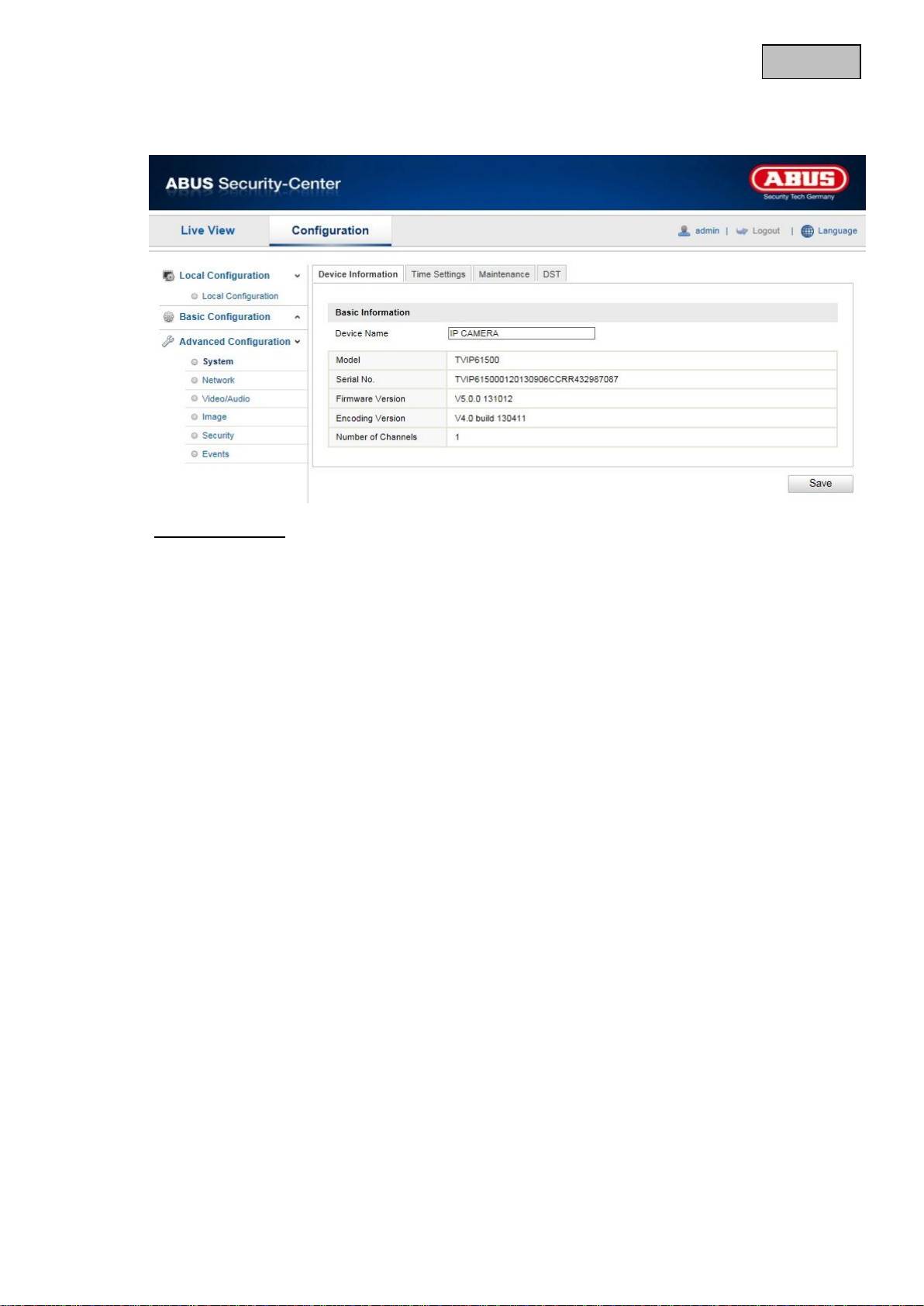
12.3.1.1 Device Information
Basic Information
Device Name
You can specify a device name for the Speed Dome here. Click on “Save” to apply the change.
Model
Model number display
Serial No.
Serial number display
Firmware Version
Firmware version display
Encoding Version
Encoding version display
Number of Channels
Display of the number of channels
70
English
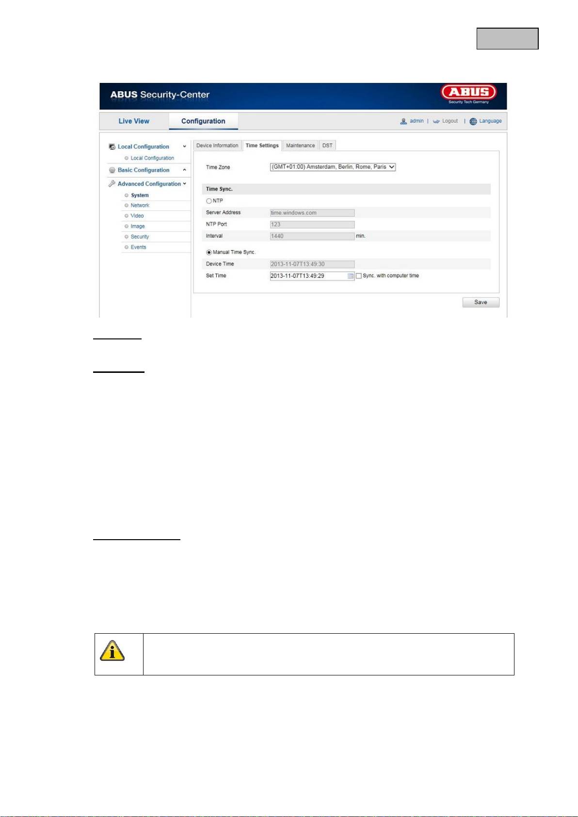
12.3.1.2 Time Settings
Time Zone
Time zone selection (GMT)
Time Sync.
NTP
Using the Network Time Protocol (NTP) it is possible to synchronise the time of the Speed Dome with
a time server.
Activate NTP to use this function.
Server Address
IP server address of the NTP server.
NTP Port
Network port number of the NTP service (default: port 123)
Manual Time Sync.
Device Time
Computer device time display
Set Time
Display of the current time using the time zone setting.
Click on “Sync. with computer time” to adopt the device time of the computer.
Apply the settings made with “Save”.

71
English
12.3.1.3 Maintenance
Reboot
Click “Reboot” to restart the device.
Default
Restore
Click “Restore” to reset all the parameters to the default settings, with the exception of the IP
parameters.
Default
Select this item to reset all parameters to the default values.
Import Config. File
Config. File
Select a file path to import a configuration file here.
Status
Display of the import status
Export Config. File
Click “Export” to export a configuration file.
Remote Upgrade
Firmware
Select the path to update the Speed Dome with new firmware.
Status
Display of the update status
Apply the settings made with “Save”.

72
English
12.3.1.4 DST
DST
Enable DST
Activate the “Enable DST” checkbox to adjust the system time automatically to summer time.
Start Time
Specify the time for switching to summer time.
End Time
Specify the time for switching to winter time.
Apply the settings made with “Save”.

73
English
12.3.2 Network
Menu item
Description
Available in mode
TCP/IP
Settings of the TCP/IP data
Basic Configuration,
Advanced
Configuration
Port
Settings for the used ports
Basic Configuration,
Advanced
Configuration
DDNS
Settings for the DDNS data
Advanced
Configuration
UPnP™
Settings for the UPnP data
Advanced
Configuration
74
English
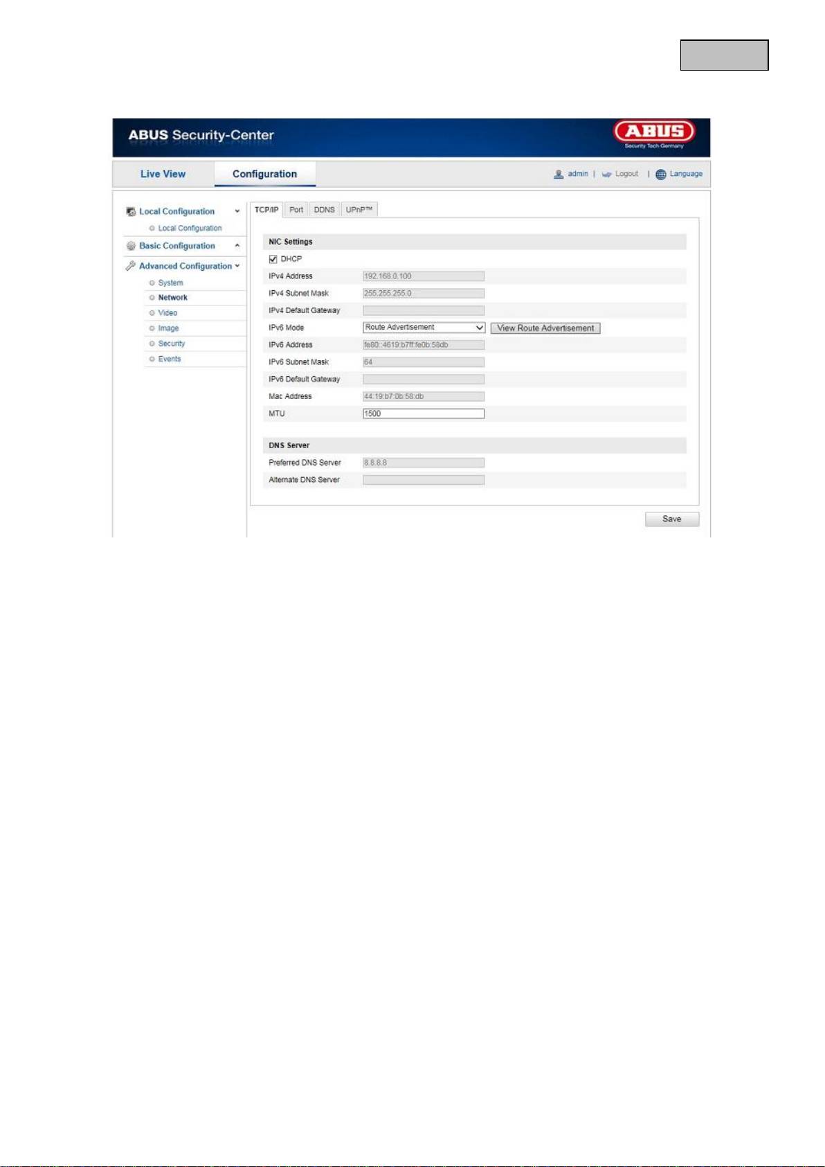
12.3.2.1 TCP/IP
To be able to operate the camera via a network, the TCP/IP settings must be configured correctly.
DHCP
If a DHCP server is available, click DHCP to apply an IP address and other network settings automatically.
The data is transferred automatically from the server and cannot be changed manually.
If no DHCP server is available, please enter the following data manually.
IPv4 Address
Setting for the IP address of the networkcamera
IPv4 Subnet Mask
Manual setting of the subnet address for the network camera
IPv4 Default Gateway
Setting for the default router for the network camera
IPv6 mode
Manual: Manual configuration of IPv6 data
DHCP: The IPv6 connection data is provided by the DHCP server (router).
Route advertisement: The IPv6 connection data is provided by the DHCP server (router) in connection with
the ISP (Internet Service Provider).
IPv6 address
Display of the IPv6 address. The address can be configured in the IPv6 “Manual” mode.
IPv6 Subnet Mask
Display of the IPv6 Subnet Mask
IPv6 Default Gateway
Display of the IPv6 Standard Gateway (standard router)
75
English
MAC Address
The IPv4 hardware address of the camera is displayed here. You cannot change it.
MTU
Setting for the transmission unit. Select a value between 500 – 9676. 1500 is set by default.
DNS Server
Preferred DNS Server
DNS server settings are required for some applications (for example, sending e-mails). Enter the address
of the preferred DNS server here.
Alternate DNS Server
If the preferred DNS server cannot be reached, this alternative DNS server is used. Please store the
address of the alternate DNS server here.
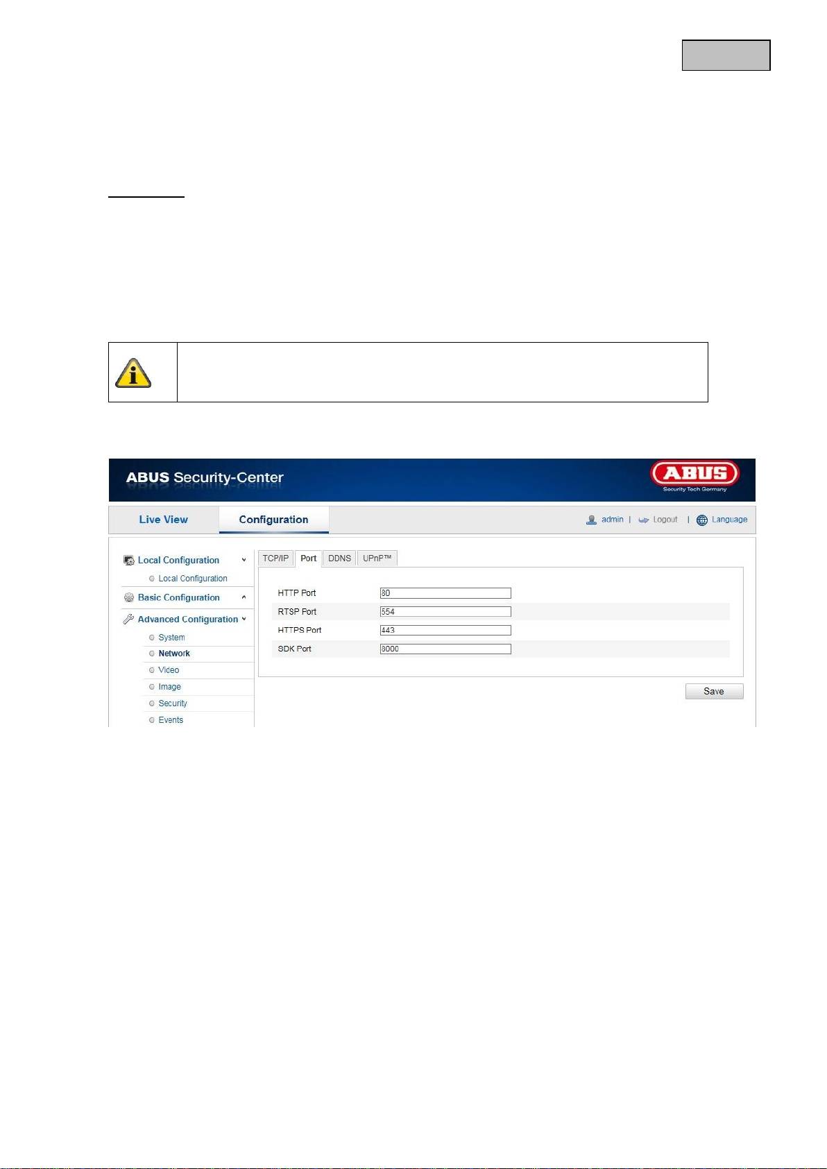
12.3.2.2 Port
If you wish to enable external access to the Speed Dome, the following ports must be configured.
HTTP Port
The standard port for HTTP transmission is 80. As an alternative, this port can be assigned a value in the
range of 1024 ~ 65535. If several network cameras are connected in the same subnetwork, then each
camera should be given a unique HTTP port of its own.
RTSP Port
The standard port for RTSP transmission is 554. As an alternative, this port can be assigned a value in the
range of 1024 ~ 65535. If several network camera are connected in the same subnetwork, then each
camera should be given a unique RTSP port of its own.
HTTPS port
The standard port for HTTPS transmission is 443.
Apply the settings made with “Save”.
76
English
SDK port (control port)
The standard port for SDK transmission is 8000. Communication port for internal data. As an alternative,
this port can be assigned a value in the range of 1025 ~ 65535. If several IP cameras are located in the
same subnetwork, then each camera should have its own unique SDK port.
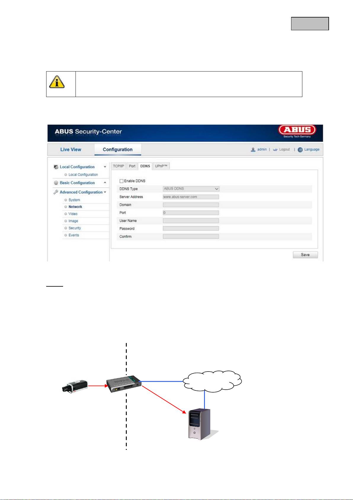
12.3.2.3 DDNS
DDNS
DynDNS or DDNS (dynamic domain name system entry) is a system that can update domain name entries
in real time. The network camera is equipped with an integrated DynDNS client that updates the IP
address independently via a DynDNS provider. If the network camera is located behind a router, we
recommend using the DynDNS function of the router.
The following diagram offers an overview of accessing and updating the IP address using DynDNS.
Apply the settings made with “Save”.
LAN
WAN
DynDNS access
data
77
English
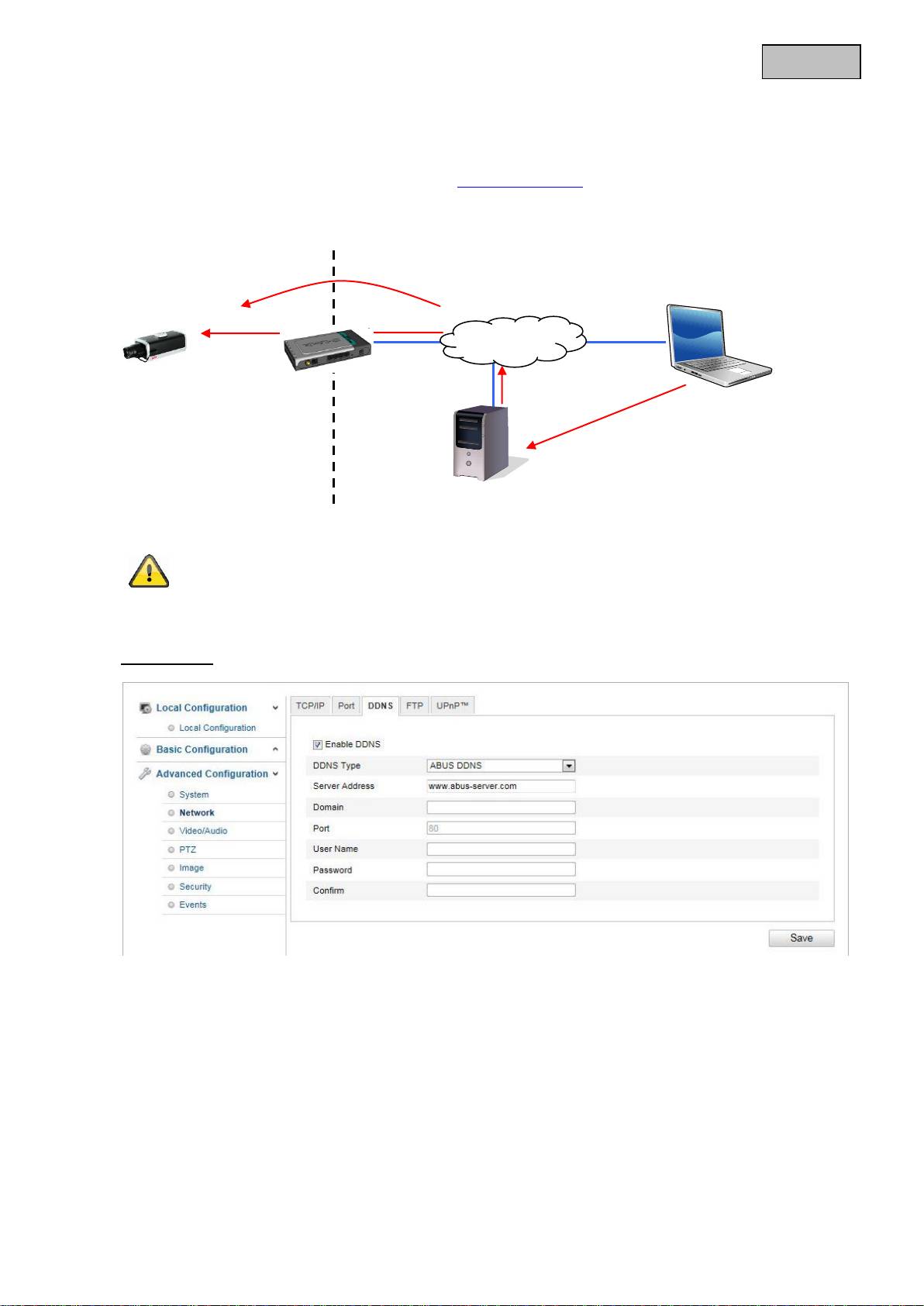
Enable DDNS
Activates or deactivates the DDNS function.
DDNS Type
Select the DDNS type. You can choose between “DynDNS” and “ABUS DDNS”.
Server Address
Select a DDNS service provider. You must have registered access to this DDNS service provider (e.g.
www.dyndns.org).
If you select “ABUS DDNS” as the DDNS type the server address is stored automatically.
Domain
Enter your registered domain name (host service) here (e.g. myIPcamera.dyndns.org).
Port
Store the port for port forwarding here.
User Name
User ID of your DDNS account
Password
Password of your DDNS account
Confirm
You need to confirm your password here.
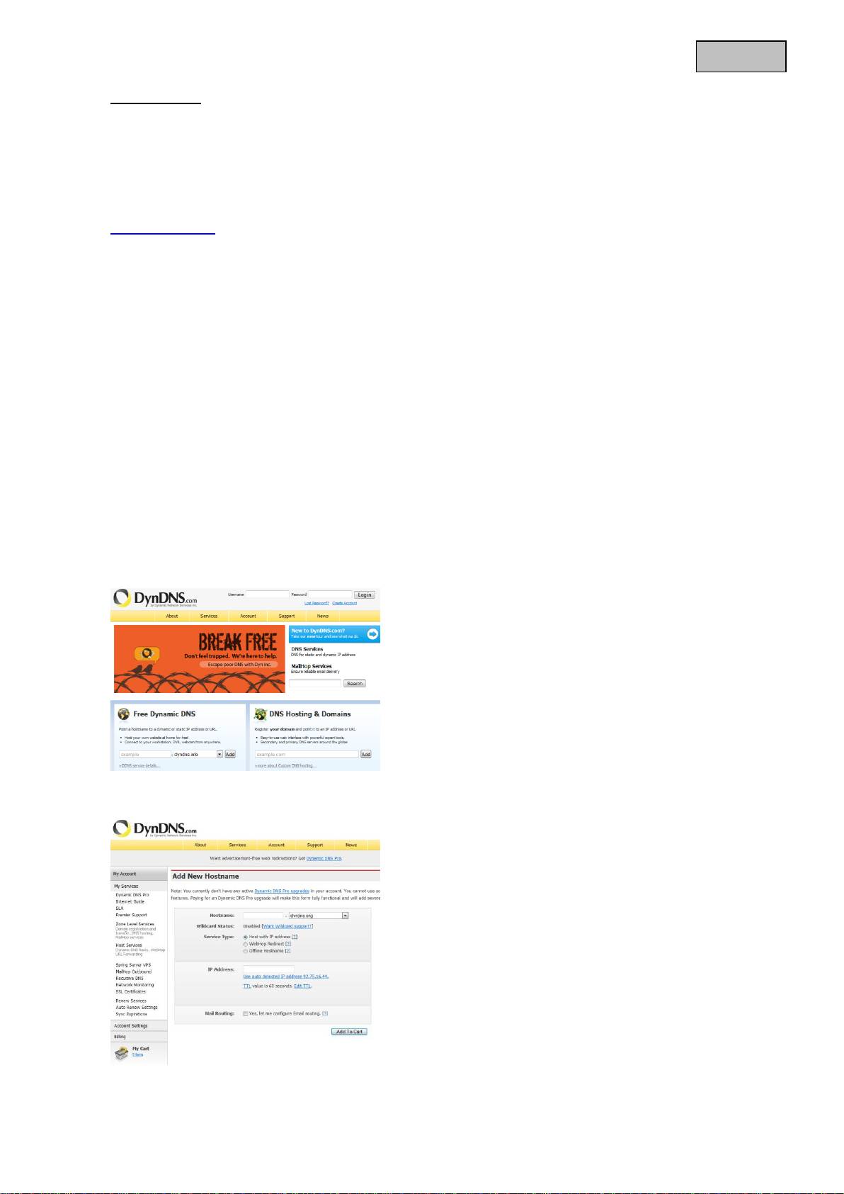
Setting up a DDNS account
Set up a new account as follows under DynDNS.org:
Store your account information:
Note down your user data and enter this into the configuration of the network camera.
78
English
Accessing the network camera over DDNS
If the network camera is located behind a router, then access via DynDNS must be configured in the
router. On the ABUS Security-Center homepage www.abus-sc.com, you can find a description of DynDNS
router configuration for common router models.
The following diagram offers an overview of accessing a network camera behind a router via DynDNS.org.
ABUS DDNS
1.
To be able to use the ABUS DDNS function, you first need to set up an account at www.abus-
server.com. Please read the FAQs on this topic on the website.
2.
Select the “Enable DDNS” checkbox and select “ABUS DDNS” as the DDNS type.
3.
Apply the data with “Save”. The IP address of your Internet connection is now updated every minute
on the server.
Port forwarding of all relevant ports (at least RTSP + HTTP) must be set up in the
router in order to use DynDNS access via the router.
DynDNS.org
Name Server
http://name.dyndns.org:1026
name.dyndns.org:1026 195.184.21.78:1026
195.184.21.78:1026
195.184.21.78:1026
192.168.0.1
LAN
WAN
Internet
79
English
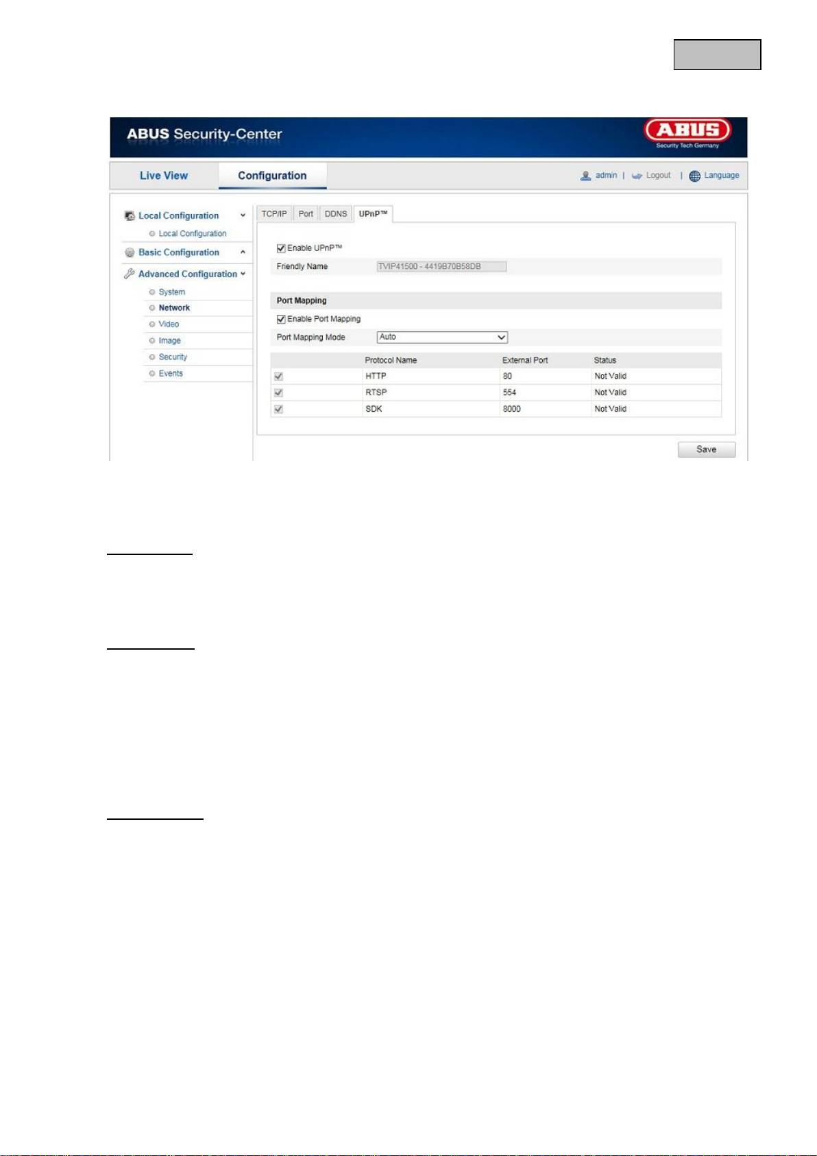
12.3.2.4 UPnP™
The UPnP (Universal Plug and Play) function makes it easy to control network devices in an IP network.
This allows the network camera to be seen in the Windows network environment (e.g. as a network
device).
Enable UPnP
For enabling or disabling the UPnP function.
Friendly Name
Display of the MAC address of the camera
Port Mapping
Enable Port Mapping
This enables Universal Plug and Play port forwarding for network services. If your router supports UPnP,
then port forwarding for video streams is activated automatically on the router for the network camera
using this option.
Port Mapping Mode
Select here whether you wish to conduct port mapping automatically or manually.
You can choose between “Auto” and “Manual”.
Protocol Name
HTTP
The standard port for HTTP transmission is 80. As an alternative, this port can be assigned a value in the
range of 1025 ~ 65535. If several IP cameras are located on the same subnetwork, then each camera
should have its own unique HTTP port.
RTSP
The standard port for RTSP transmission is 554. As an alternative, this port can be assigned a value in the
range of 1025 ~ 65535. If several IP cameras are located in the same subnetwork, then each camera
should have its own unique RTSP port.
SDK (control port)
The standard port for SDK transmission is 8000. Communication port for internal data. As an alternative,
this port can be assigned a value in the range of 1025 ~ 65535. If several IP cameras are located in the
same subnetwork, then each camera should have its own unique SDK port.

80
English
External Port
You can only change ports manually here of the “Port Mapping Mode” was set to manual.
Status
Displays whether the external port entered is valid or invalid.
12.3.3 Video
Menu item
Description
Available in mode
Video
Settings for video output
Basic Configuration,
Advanced
Configuration
Apply the settings made with “Save”.
