Indesit VRA 640 X: instruction
Class: Household, kitchen appliances, electronics and equipment
Type:
Manual for Indesit VRA 640 X
English
GB
Operating Instructions
HOB
Contents
Operating Instructions,1
Description of the appliance-Control Panel,2
Installation,6
Start-up and use,9
Precautions and tips,12
Care and maintenance,13
Technical description of the models,13
FR
Français
Mode d’emploi
TABLE DE CUISSON
Sommaire
Mode d’emploi,1
Description de l’appareil-Tableau de bord, 2
Installation,14
Mise en marche et utilisation,17
Précautions et conseils, 20
Nettoyage et entretien,21
Description technique des modèles,21
Español
ES
Manual de instrucciones
ENCIMERA
Sumario
Manual de instrucciones,1
Descripción del aparato-Panel de control,2
Instalación,22
Puesta en funcionamiento y uso,25
Precauciones y consejos,28
Mantenimiento y cuidados,29
Descripción técnica de los modelos,29
Instruções para a utilização
PLANO
Índice
Instruções para a utilização,1
Descrição do aparelho-Painel de comandos,2
Instalação, 30
Início e utilização, 33
Precauções e conselhos,36
Manutenção e cuidados,37
Descrição técnica dos modelos,37
PT
Português
DE
Bedienungsanleitung
KOCHFELD
Inhaltsverzeichnis
Bedienungsanleitung,1
Beschreibung des Gerätes- Bedienfeld,2
Installation, 38
Inbetriebsetzung und Gebrauch,41
Vorsichtsmaßregeln und Hinweise, 44
Reinigung und Pflege, 45
Technische Beschreibung der Modelle, 45
NL
PL
RS
Italiano
IT
Istruzioni per l’uso
PIANO COTTURA
Sommario
Istruzioni per l’uso,1
Descrizione dell’apparecchio- Pannello di controllo,2
Installazione, 46
Avvio e utilizzo,49
Precauzioni e consigli,52
Manutenzione e cura,53
Descrizione tecnica dei modelli,53
Deutsch
Nederland
Gebruiksaanwijzing
KOOKPLAAT
Inhoud
Gebruiksaanwijzing,1
Beschrijving van het apparaat-Bedieningspaneel,2
Installatie, 54
Starten en gebruik, 57
Voorzorgsmaatregelen en advies,60
Onderhoud en verzorging,60
Technische beschrijving van de modellen,61
Polski
Instrukcja obs
ł
ugi
P
Ł
YTA GRZEJNA
Spis tre
ś
ci
Instrukcja obs
ł
ugi,1
Opis urz
ą
dzenia-Panel sterowania,2
Instalacja,62
Uruchomienie i u
ż
ytkowanie,65
Zalecenia i
ś
rodki ostro
ż
no
ś
ci,68
Konserwacja i utrzymanie,69
Opis Techniczny,69
,1
,2
Монтаж
,71
B
арочная
панель
,73
Предосторожности
и
рекомендации
,77
Техническое
обслуживание
и
уход
,78
Техническое
обслуживание
,78
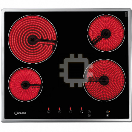
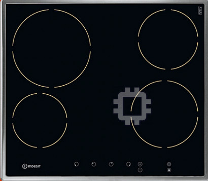
VEA 645 D C
VRA 631 T B
VRA 631 T X
VRA 640 C
VRA 640 X
VRA 641 D B
VRA 641 D C
VRA 641 D X
Русский
Руководство по эксплуатации
ВАРОЧНАЯ ПАНЕЛЬ
Содержание
Руководство по эксплуатации
Описание изделия-Панель управления
2
Description of the appliance
Control panel
GB
Description de l’appareil
Tableau de bord
FR
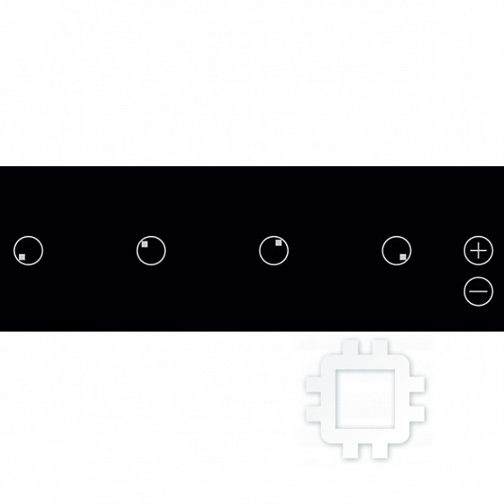
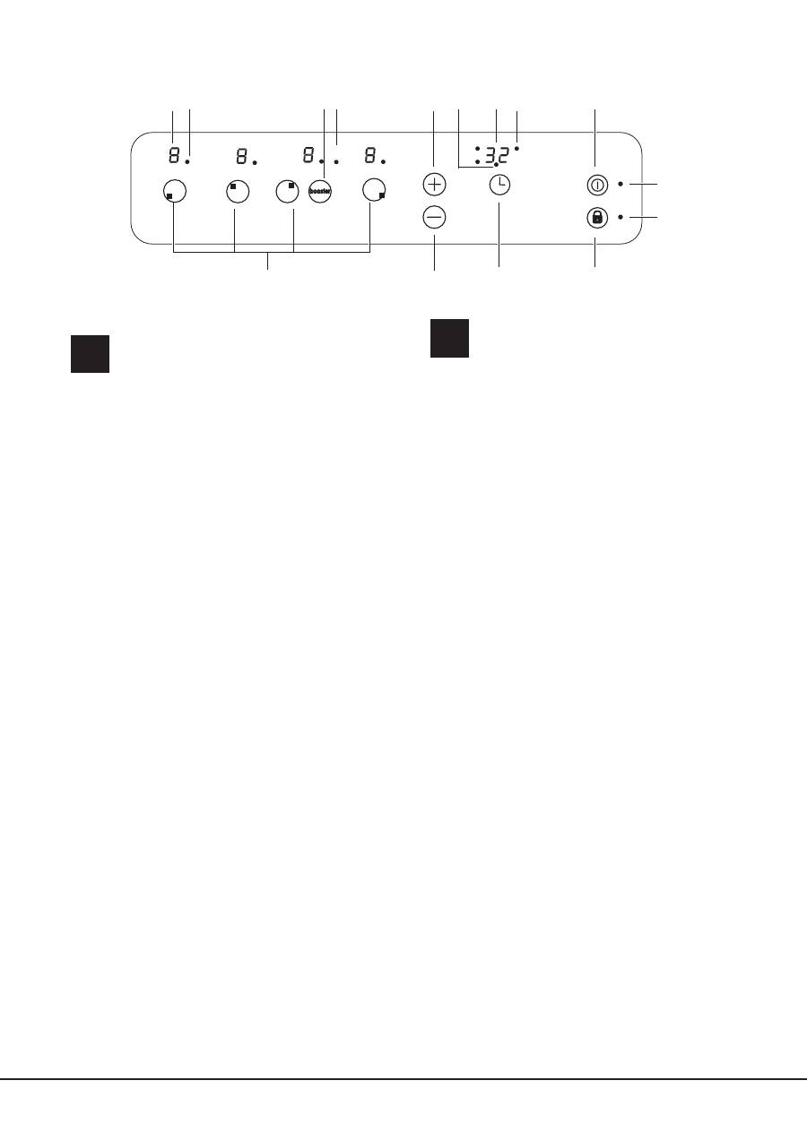
The control panel described in this manual is only a
representative example: it may not exactly match the panelon
your appliance.
1
INCREASE POWER
button switches on the hotplate
and controls the power (
see Start-up and use
).
2
REDUCE POWER
button controls the power and
switches off the hotplate (
see Start-up and use
).
3
COOKING ZONE SELECTOR
indicator shows a
particular cooking zone has been selected and
therefore various adjustments are possible.
4
COOKING ZONE SELECTOR
button is used to
select the desired cooking zone.
5
POWER
indicator provides a visual display for the
current heat level.
6
ON/OFF
button switches the appliance on and off.
7
ON/OFF
indicator light shows whether the appliance
is on or off.8
CONTROL PANEL LOCK
button
prevents accidental changes to the hob settings (
see
Start-up and use
).
9
CONTROL PANEL LOCK
indicator light shows the
control panel has been locked (
see Start-up and use
).
! This product complies with the requirements of the
latest European Directive on the limitation of power
consumption of the standby mode.
If no operations are carried out for a period of 2
minutes, after the residual heat indicator lights turn
off and the fan stops (if present), the appliance
automatically switches to the .off mode..
The appliance resumes the operating mode once the
ON/OFF button is pressed.
Le tableau de bord qui est
décrit n.a qu.une valeur d.exemple :
il peut ne pas correspondre au modèle acheté
.
1 Touche
AUGMENTATION DE PUISSANCE
pour
allumer le foyer et régler sa puissance (
voir Mise en
marche et utilisation
).
2 Touche
DIMINUTION DE PUISSANCE
pour régler la
puissance et éteindre le foyer (
voir Mise en marche et
utilisation
).
3 Voyant
FOYER SELECTIONNÉ
pour signaler que
le foyer correspondant a été sélectionné et que les
régulations sont donc possibles.
4 Touche
SÉLECTION FOYER
pour sélectionner le
foyer souhaité
5 Indicateur de
PUISSANCE
: une colonne lumineuse
pour signaler le niveau de puissance atteint.
6 Touche
ON/OFF
pour allumer ou éteindre l’appareil.
7 Voyant
ON/OFF
: il signale si l’appareil est allumé ou
éteint.
8 Touche
VERROUILLAGE DES COMMANDES
pour empêcher toute intervention extérieure sur les
réglages de la table de cuisson (
voir
Mise en marche
et Utilisation
).
9 Voyant
COMMANDES VERROUILLÉES
: pour
signaler le verrouillage des commandes (
voir Mise en
marche et Utilisation
).
!
Ce produit est conforme à la nouvelle Directive
Européenne sur la réduction de la consommation
d’énergie en mode standby.
Sans opérations pendant 2 minutes, après
l’extinction des voyants de chaleur résiduelle et
l’arrêt du ventilateur (si existants), l’appareil se place
automatiquement en „off mode”.
Pour remettre l’appareil en mode de fonctionnement
normal, appuyer sur la touche ON/OFF.
13
1
2
3
5
4
6
7
8
9 10
11
12
14
15

GB
3
Descripción del aparato
Panel de control
ES
Descrição do aparelho
Painel de comandos
PT
El panel de control se describe a continuación a modo de
ejemplo: puede no ser una exacta reproducción del
modelo adquirido.
1 Botón
AUMENTO DE POTENCIA
para encender
la placa y regular la potencia (
ver Puesta en
funcionamiento y uso
).
2 Botón
DISMINUCIÓN DE POTENCIA
para regular
la potencia y apagar la placa (
ver Puesta en
funcionamiento y uso
).
3 Piloto
ZONA DE COCCIÓN SELECCIONADA
indica
que ha sido seleccionada dicha zona de cocción
y, por lo tanto, se pueden realizar las distintas
regulaciones
4 Botón
SELECCIÓN DE ZONA DE COCCIÓN
para
seleccionar la zona de cocción deseada
5 Indicador de
POTENCIA
: indica visualmente el nivel
de calor alcanzado.
6 Botón
ON/OFF
para encender y apagar el aparato.
7 Piloto
ON/OFF
: indica si el aparato está encendido o
apagado.
8 Botón
BLOQUEO DE MANDOS
para impedir
modificaciones fortuitas a las regulaciones de la
encimera (
ver
Puesta en funcionamiento y uso
).
9 Piloto
MANDOS BLOQUEADOS
: indica que se ha
producido el bloqueo de los mandos (
ver Puesta en
funcionamiento y uso
).
! Este producto satisface los requisitos establecidos
por la nueva Directiva europea sobre la limitación de
los consumos energéticos en standby.
Si no se realizan operaciones por 2 minutos, una vez
que se apagan los luces piloto del calor residual y
del ventilador (si están presentes), el aparato se
coloca de forma automática en el modo .off mode..
El aparato vuelve al modo operativo utilizando la
tecla ON/OFF.
O painel de comandos descrito a seguir está representado para
fins explicativos: pode não ser uma exacta
reprodução do modelo comprado.
1 Botão
AUMENTO POTÊNCIA
para ligar a chapa e
regular a potência (
veja Início e utilização
).
2 Botão
DIMINUIÇÃO POTÊNCIA
para regular a
potência e desligar a chapa (
veja Início e utilização
).
3 Indicador luminoso
ZONA DE COZEDURA
SELECCIONADA
indica que a zona de cozedura
relativa foi seleccionada e são portanto possíveis as
várias regulações.
4 Botão
SELECÇÃO ZONA DE COZEDURA
para
seleccionar a zona de cozedura desejada.
5 Indicador
POTÊNCIA
sinaliza visualmente o nível de
calor alcançado.
6 Botão
ON/OFF
para ligar e desligar o aparelho.
7 Indicador
ON/OFF
: sinaliza se o aparelho está
aceso ou apagado.
8 Botão
BLOQUEIO DOS COMANDOS
para impedir
modificações acidentais das regulações do plano
de cozedura (
veja Início e utilização
).
9 Indicador luminoso
COMANDOS BLOQUEADOS
:
sinaliza o bloqueio dos comandos (
veja Início e
utilização
).
! Este produto satisfaz os requisitos impostos pela
nova Directiva Europeia sobre a limitação dos
consumos energéticos em stand-by.
Se não se efectuarem operações por 2 minutos,
depois que os indicadores de calor resíduo e da
ventoinha (se presentes) se desligarem, o aparelho
coloca-se automaticamente na modalidade .off
mode..
O aparelho voltará para a modalidade operativa ao
carregar na tecla ON/OFF.
DE
Beschreibung des Gerätes
Bedienfeld
Das hier beschriebene Bedienfeld dient nur als Beispiel,
es handelt sich nicht unbedingt um eine genaue
Widergabe des von Ihnen erworbenen Modells.
1 Taste
ERHÖHEN DER LEISTUNG:
Zum Einschalten
sowie zur Leistungsregelung der Kochzone (
siehe
Inbetriebsetzung und Gebrauch
).
2 Taste
HERABSETZEN DER LEISTUNG:
Zur
Leistungsregelung sowie zum Ausschalten der
Kochzone (
siehe Inbetriebsetzung und Gebrauch
).
3 Kontrollleuchte
GEWÄHLTE KOCHZONE:
Diese zeigt an, dass die der Kontrollleuchte
entsprechende Kochzone gewählt wurde und die
gewünschten Einstellungen demnach vorgenommen
werden können.
4 Taste
WAHL DER KOCHZONE:
Mittels dieser wird
die gewünschte Kochzone gewählt.
5 LEISTUNGSANZEIGE: Auf dieser ist der jeweils
erreichte Heizwert ersichtlich.
6 Taste
ON/OFF:
Zum Ein- bzw. Ausschalten des
Gerätes.
7 Kontrollleuchte
ON/OFF:
Diese zeigt an, ob das
Gerät ein- oder ausgeschaltet ist.
8 Taste
SPERRE DER SCHALTELEMENTE:
Um
versehentliche Änderungen der am Kochfeld
erfolgten Einstellungen zu verhindern (
siehe
Inbetriebsetzung und Gebrauch
).
9 Kontrollleuchte
SCHALTELEMENTE GESPERRT:
Diese signalisiert, dass die Schaltelemente gesperrt
wurden (
siehe Inbetriebsetzung und Gebrauch
).
! Dieses Produkt entspricht den Vorschriften der
neuen Europäischen Richtlinie zur Einschränkung des
Energieverbrauchs im Standby. Werden für 2 Minuten keine
Tasten gedrückt, dann stellt sich das Gerät nach Ausschalten
der Anzeigen für Resthitze und des Lüfters (wenn vorhanden)
automatisch in den “off mode”. Das Gerät kehrt durch Drücken
der Taste ON/OFF in den Betriebsmodus zurück.

4
IT
Il pannello di controllo che qui viene descritto è
rappresentato a fini esemplificativi: può non essere una
esatta riproduzione del modello acquistato.
1 Tasto
AUMENTO POTENZA
per accendere la
piastra e regolare la potenza (
vedi Avvio e utilizzo
).
2 Tasto
DIMINUZIONE POTENZA
per regolare la
potenza e spegnere la piastra (
vedi Avvio e utilizzo
).
3 Spia
ZONA DI COTTURA SELEZIONATA
indica
che la zona di cottura relativa è stata selezionata e
quindi sono possibili le varie regolazioni
4 Tasto
SELEZIONE ZONA DI COTTURA
per
selezionare la zona di cottura desiderata
5 Indicatore
POTENZA
: segnala visivamente il livello
di calore raggiunto.
6 Tasto
ON/OFF
per accendere e spegnere
l’apparecchio.
7 Spia
ON/OFF
: segnala se l’apparecchio è acceso
o
spento.
8 Tasto
BLOCCO DEI COMANDI
per impedire
modifiche fortuite alle regolazioni del piano cottura
(
vedi
Avvio e utilizzo
).
9 Spia
COMANDI BLOCCATI
: segnala l’avvenuto
blocco dei comandi (
vedi Avvio e utilizzo
).
!
Questo prodotto soddisfa i requisiti imposti dalla nuova
Direttiva Europea sulla limitazione dei consumi energetici in
standby. Se non si eseguono operazioni per 2 minuti, dopo
lo spegnimento delle spie di calore residuo e della ventola
(ove presenti), l’apparecchio si dispone automaticamente
in modalità “off mode”. L’apparecchio ritorna in modalità
operativa agendo sul tasto ON/OFF.
Descrizione dell’apparecchio
Pannello di controllo
NL
Beschrijving van het apparaat
Bedieningspaneel
Het bedieningspaneel dat hier wordt beschreven en afgebeeld geldt
alleen als voorbeeld: het is mogelijk dat het niet exact overeenkomt met
het door u aangeschafte model.
1 Toets
TOENAME VERMOGEN
om de kookplaat
aan te zetten en het vermogen ervan te regelen (
zie
Starten en gebruik
).
2 Toets
AFNAME VERMOGEN
om het vermogen te
regelen en de kookplaat uit te zetten (
zie Starten en
gebruik
).
3 Controlelampje
GESELECTEERD
KOOKGEDEELTE
geeft aan dat het betreffende
kookgedeelte geselecteerd is en dat u het kunt
regelen.
4 Toets
SELECTEREN KOOKGEDEELTE
om het
gewenste kookgedeelte te selecteren
5 Aanwijzer
VERMOGEN
: geeft het bereikte
warmteniveau aan.
6 Toets
ON/OFF
voor het in- en uitschakelen van het
apparaat.
7 Controlelampje
ON/OFF
: geeft aan of het apparaat
in- of uitgeschakeld is.
8 Toets
BLOKKERING BEDIENINGSPANEEL
om
te voorkomen dat er ongewilde wijzigingen aan de
regeling van het kookvlak worden uitgevoerd (
zie
Starten en gebruik
).
9 Controlelampje
BLOKKERING
BEDIENINGSPANEEL
: toont dat de blokkering van
het bedieningspaneel heeft plaatsgevonden (
zie
Starten en gebruik
).
!
Dit product voldoet aan de eisen die gesteld worden door de
nieuwe Europese Richtlijn voor energiebesparing voor apparaten
in de standby-stand.
Wanneer 2 minuten lang geen handelingen worden uitgevoerd
gaat het apparaat, na het uitgaan van de waarschuwingslampjes
voor restwarmte en voor de ventilator (indien aanwezig),
automatisch in de “off mode”.
Door op de ON/OFF toets te drukken, keert het apparaat weer
terug in de operationele stand.
PL
Opis urz
ą
dzenia
Panel sterowania
Opisany tu panel sterowania jest przedstawiony jako
przyk
ł
ad: nie musi by
ć
dok
ł
adnie taki sam, jak panel
zainstalowany w zakupionym urz
ą
dzeniu.
Przycisk
ZWIEKSZENIA MOCY
do wlaczania plyty i
do regulacji mocy (
patrz Uruchomienie i uzytkowanie
).
2 Przycisk
ZMNIEJSZENIA MOCY
do regulacji
mocy i do wylaczania plyty (
patrz Uruchomienie i
uzytkowanie
).
3 Kontrolka
WYBRANEGO POLA GRZEJNEGO
wskazuje, ze dane pole grzejne zostalo wybrane, a
wiec mozliwe sa rózne regulacje
4 Przycisk
WYBORU POLA GRZEJNEGO
do
wybrania zadanego pola grzejnego.
5 WskaŸnik
MOCY
: wizualnie sygnalizuje osi¹gniêty
poziom ciep³a.
6 Przycisk
ON/OFF
do wlaczania i wylaczania
urzadzenia.
7 Kontrolka
ON/OFF
: sygnalizuje, czy urzadzenie jest
wlaczone, czy wylaczone.
8 Przycisk
BLOKADY STEROWANIA
do
zapobiegania przypadkowym zmianom parametrów
przy regulacji plyty grzejnej (
patrz
Uruchomienie i
uzytkowanie
).
9 Kontrolka
BLOKADY STEROWANIA
: sygnalizuje
zablokowanie sterowania (
patrz Uruchomienie i
uzytkowanie
).
! Ten produkt spe
ł
nia wymogi dyrektywy wspólnotowej
dotycz
ą
cej ograniczenia zu
ż
ycia energii w trybie czuwania.
Je
ś
li przez 2 minuty nie s
ą
wykonywane
ż
adne operacje,
po wy
łą
czeniu wska
ź
nika ciep
ł
a resztkowego i wentylatora
(je
ś
li obecne), urz
ą
dzenie automatycznie przechodzi w tryb
„off mode”.Urz
ą
dzenie powraca do trybu aktywnego po
naci
ś
ni
ę
ciu przycisku ON/OFF.

GB
5
RS
Описание
изделия
Панель
управления
Панель
управления
,
описание
которои
приводится
ниже
,
служит
только
в
качестве
примера
:
она
может
не
в
точности
соответствовать
Вашеи
модели
1
Кнопка
УВЕЛИЧЕНИЕ
МОЩНОСТИ
служит
для
включения
варочнои
зоны
и
регуляции
мощности
нагрева
(
см
.
Включение
и
эксплуатация
).
2
Кнопка
УМЕНЬШЕНИЕ
МОЩНОСТИ
служит
для
регуляции
мощности
и
выключения
варочнои
зоны
(
см
.
Включение
и
эксплуатация
).
3
Индикатор
ВЫБРАННАЯ
ВАРОЧНАЯ
ЗОНА
показывает
,
что
соответствующая
варочная
зона
была
выбрана
и
следовательно
возможно
произвести
настроики
ее
функции
.
4
Кнопка
ВЫБОР
ВАРОЧНОИ
ЗОНЫ
служит
для
выбора
нужнои
варочнои
зоны
.
5
Индикатор
МОЩНОСТЬ
:
показывает
уровень
нагрева
.
6
Кнопка
ON/OFF (
ВКЛ
./
ВЫКЛ
.)
служит
для
включения
и
выключения
изделия
.
7
Индикатор
ON/OFF (
ВКЛ
./
ВЫКЛ
.)
:
показывает
состояние
изделия
,
включено
или
выключено
.
8
Кнопка
БЛОКИРОВКА
УПРАВЛЕНИИ
служит
для
защиты
управлении
варочнои
панели
от
случаиных
измнении
(
см
.
Включение
и
эксплуатация
).
9
Индикатор
УПРАВЛЕНИЯ
ЗАБЛОКИРОВАНЫ
показывает
,
что
управления
заблокированы
(
см
.
Включение
и
эксплуатация
).
!
Данное
изделие
отвечает
требованиям
новой
Европейской
Директивы
по
ограничению
энергопотребления
в
режиме
энергосбережения
.
Если
в
течение
2-
х
минут
не
производится
никаких
действий
после
выключения
индикаторов
остаточного
тепла
и
вентилятора
(
если
они
присутствуют
),
изделие
автоматически
переходит
в
режим
«
ВЫКЛ
.».
Возврат
изделия
в
рабочий
режим
производится
кнопкой
ВКЛ
./
ВЫКЛ
.
6
GB
Installation
!
Before operating your new appliance please read
this instruction booklet carefully. It contains important
information concerning the safe operation, installation
and maintenance of the appliance.
!
Please keep these operating instructions for future
reference. Pass them on to any new owners of the
appliance.
Positioning
!
Keep all packaging material out of the reach of
children. It may present a choking or suffocation
hazard (
see Precautions and tips
).
!
The appliance must be installed by a qualified
professional in accordance with the instructions
provided. Incorrect installation may cause harm to
people and animals or may damage property.
Built-in appliance
Use a suitable cabinet to ensure that the appliance
functions properly.
• The supporting surface must be heat-resistant up to
a temperature of approximately 100°C.
• If the appliance is to be installed above an oven,
the oven must be equipped with a forced ventilation
cooling system.
• Avoid installing the hob above a dishwasher: if this
cannot be avoided, place a waterproof separation
device between the two appliances.
• Depending on the hob you want to install, the
cabinet must have the following dimensions (
see
fi gure
):
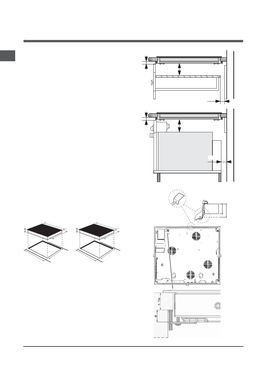
560 +/- 1
490 +/- 1
48
590
520
560 +/- 1
490 +/- 1
48
574
504
Ventilation
To allow adequate ventilation and to avoid overheating of
the surrounding surfaces the hob should be positioned as
follows:
• At a minimum distance of 40 mm from the back
panel.
• So that a minimum distance of 20 mm is maintained
between the installation cavity and the cabinet
underneath.
• Kitchen cabinets adjacent to the appliance and taller
than the top of the hob must be at least 600 mm
from the edge of the hob.
FRONT SIDE
OF HOB
SUPPORTING
SURFACE
30
40
UNDERSIDE
OF HOB
5 mm
min. 20 mm
min. 20 mm
min. 40 mm
COMPARTMENT
5 mm
min. 40 mm
FAN-ASSISTED
OVEN
7
GB
Fixing
The appliance must be installed
on a perfectly level
supporting surface.
Any deformities caused by improper fixing could affect
the features and operation of the hob.
The thickness of the supporting surface should be taken
into account when choosing
the length of the screws for
the fixing hooks:
• 30 mm thick: 17.5 mm screws
• 40 mm thick: 7.5 mm screws
Fix the hob as follows:
1. Use short flat-bottomed screws to fix the 4 alignment
springs in the holes provided at the central point of
each side of the hob.
2. Place the hob in the cavity, make sure it is in a
central position and push down on the whole perimeter
until the hob is stuck to the supporting surface.
3. For hobs with raised sides: After inserting the hob
into its cavity, insert the 4 fixing hooks (each has its
own pin) into the lower edges of the hob, using the
long pointed screws to fix them in place, until the glass
is stuck to the supporting surface.
!
The screws for the alignment springs must remain
accessible.
!
In order to adhere to safety standards, the appliance
must not come into contact with electrical parts once it
has been installed.
!
All parts which ensure the safe operation of the
appliance must not be removable without the aid of a
tool.
Electrical connection
!
The electrical connection for the hob and for any built-
in oven must be carried out separately, both for safety
purposes and to make extracting the oven easier.
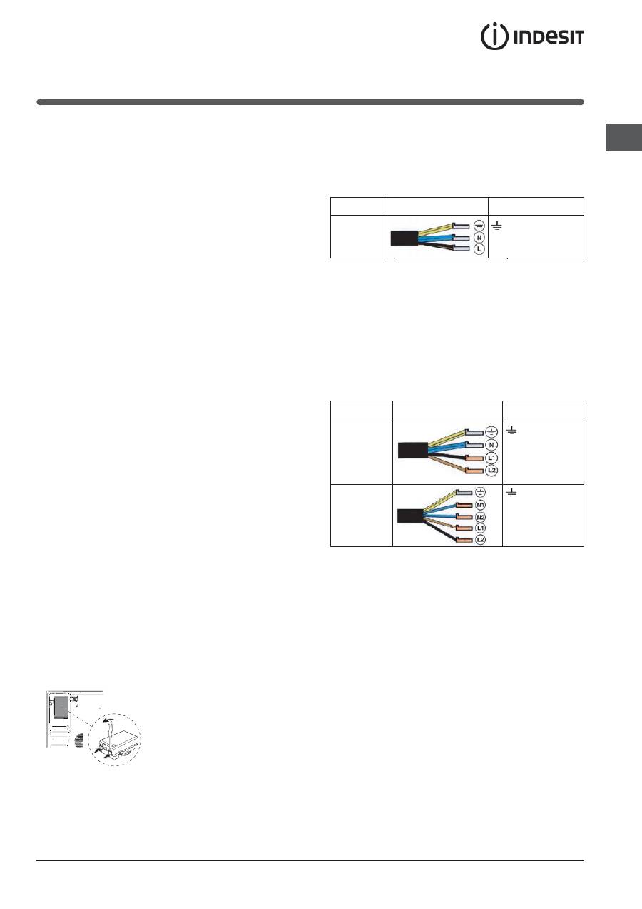
Terminal board
On the lower part of the
appliance there is a connection
box for the different types of
electricity supply (the picture
is only an indication and is not
an exact representation of the
purchased model).
Single-phase connection
The hob is equipped with a pre-connected electricity
supply cable, which is designed for single-phase
connection. Connect the wires in accordance with the
instructions given in the following table and diagrams:
Voltage and
mains frequency
Electrical cable
Wire connection
230-240V 1+N ~
220-240V 1+N ~
50/60 Hz
: yellow/green
N
: the two blue wires together
L
: brown and black together
Other types of connection
If the mains supply corresponds with one of the
following:
Voltage and mains frequency
• 400V - 2+N ~ 50/60 Hz
• 220-240V 3 ~ 50/60 Hz
• 230-240V 3 ~ 50/60 Hz
• 400V - 2+2N ~ 50/60 Hz
Separate the wires and connect them in accordance with
the instructions given in the following table and diagrams:
Voltage and
mains frequency
Electrical cable
Wire connection
400V - 2+N ~
50/60 Hz
230-240V 3 ~
220-240V 3 ~
50/60 Hz
: yellow/green;
N
: the two blue wires
together
L1
: black
L2
: brown
400V - 2+2N ~
50/60 Hz
: yellow/green;
N1
: blue
N2
: blue
L1
: black
L2
: brown
If the mains supply corresponds with one of the
following:
Voltage and mains frequency
• 400V 3 - N ~ 50/60 Hz
proceed as follows:
!
The cable provided is not suitable for the following
types of installation.
1. Use a suitable supply cable, H05RR-F or higher, with
the right dimensions (cable cross section: 25 mm).
2. To open the terminal board, use a screwdriver as
a lever under the side tabs of the cover (
see Terminal
board picture
).
3. Loosen the cable clamp screw and the terminal
board screws in accordance with the type of
connection required and position the connection
supports as shown in the following table and diagrams.
4. Position the wires in accordance with the information
given in the following table and diagrams and connect
the appliance by tightening all the screws for the
springs as much as possible.
UNDERSIDE OF HOB
8
GB
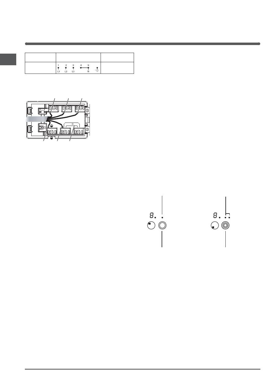
Voltage and
mains frequency
Electrical connections
Terminal board
400V 3-N ~
50/60 Hz
Three-phase 400
5. Secure the power supply cable by fastening the
cable clamp screw, then put the cover back on.
Three-phase 400
U-bolt
connection support
Neutral
Earth
Phase
Phase
Phase
1
2
3
5
4
Connecting the electricity supply cable to the mains
If the appliance is being connected directly to the
electricity mains an omnipolar switch must be installed
with a minimum opening of 3 mm between contacts.
!
The installer must ensure that the correct electrical
connection has been made and that it is fully compliant
with safety regulations.
Before connecting the appliance to the power supply,
make sure that:
• The appliance is earthed and the plug is compliant
with the law.
• The socket can withstand the maximum power of
the appliance, which is indicated on the data plate
located on the appliance itself.
• The voltage falls within the range of values indicated
on the data plate.
• The socket is compatible with the plug of the
appliance. If the socket is incompatible with the plug,
ask an authorised technician to replace it. Do not use
extension cords or multiple sockets.
!
Once the appliance has been installed, the power
supply cable and the electrical socket must be easily
accessible.
!
The cable must not be bent or compressed.
!
The cable must be checked regularly and replaced by
authorised technicians only.
!
The manufacturer declines any liability should
these safety measures not be observed.
!
Do not remove or replace the power supply cable
for any reason. Its removal or replacement will void
the warranty and the CE marking. INDESIT does not
assume liability for accidents or damage arising from
replacement/removal of the original power supply
cable. Replacement can only be accepted when
carried out by personnel authorised by INDESIT and
using an original spare part.
Extendable cooking zones
Certain models are fitted with extendable cooking
zones. These may be circular and may vary in their
extensibility (they may be double or triple hotplates). A
list of controls is given below (these controls are only
present in models with the extendable cooking zone
option).
Circular extendable hotplate
•
DOUBLE HOTPLATE ON
button switches on the
double hotplate (
see Start-up and use
).
•
DOUBLE HOTPLATE ON indicator light shows
the double hotplate has been switched on.
•
TRIPLE HOTPLATE ON
button switches on the
triple hotplate (
see Start-up and use
).
•
TRIPLE HOTPLATE ON indicator light shows the
triple hotplate has been switched on.
DOUBLE
HOTPLATE ON
indicator light
DOUBLE
HOTPLATE ON
button
TRIPLE
HOTPLATE ON
indicator light
TRIPLE
HOTPLATE ON
button
Table of contents
- Installation
- Start-up and use
- Precautions and tips
- Care and maintenance
- Installation
- Mise en marche et utilisation
- Précautions et conseils
- Nettoyage et entretien
- Instalación
- Puesta en funcionamiento y uso
- Precauciones y consejos
- Mantenimiento y cuidados
- Instalação
- Início e utilização
- Precauções e conselhos
- Manutenção e cuidados
- Installation
- Inbetriebsetzung und Gebrauch
- Vorsichtsmaßregeln und Hinweise
- Reinigung und Pflege
- Installazione
- Avvio e utilizzo
- Precauzioni e consigli
- Manutenzione e cura
- Installatie
- Starten en gebruik
- Voorzorgsmaatregelen en advies
- Onderhoud en verzorging
- Instalacja
- Uruchomienie i u ż ytkowanie
- Zalecenia i ś rodki ostro ż no ś ci
- Konserwacja i utrzymanie
- Монтаж
- Включение и эксплуатация
- Предосторожности и рекомендации
- Техническоеобслуживани и уход


